
Controllable backlight structure and display device

a display device and control scheme technology, applied in static indicating devices, instruments, non-linear optics, etc., can solve the problems of large power consumption, complex backlight control scheme and structure of existing liquid crystal display devices, and inability to save energy, so as to improve the display of liquid crystal image screen, improve the display effect, and achieve the effect of simple and easy control of backlight structur

Inactive Publication Date: 2020-04-30
HUIZHOU CHINA STAR OPTOELECTRONICS TECHNOLOGY CO LTD
View PDF4 Cites 1 Cited by
  • Summary
  • Abstract
  • Description
  • Claims
  • Application Information

AI Technical Summary

Benefits of technology

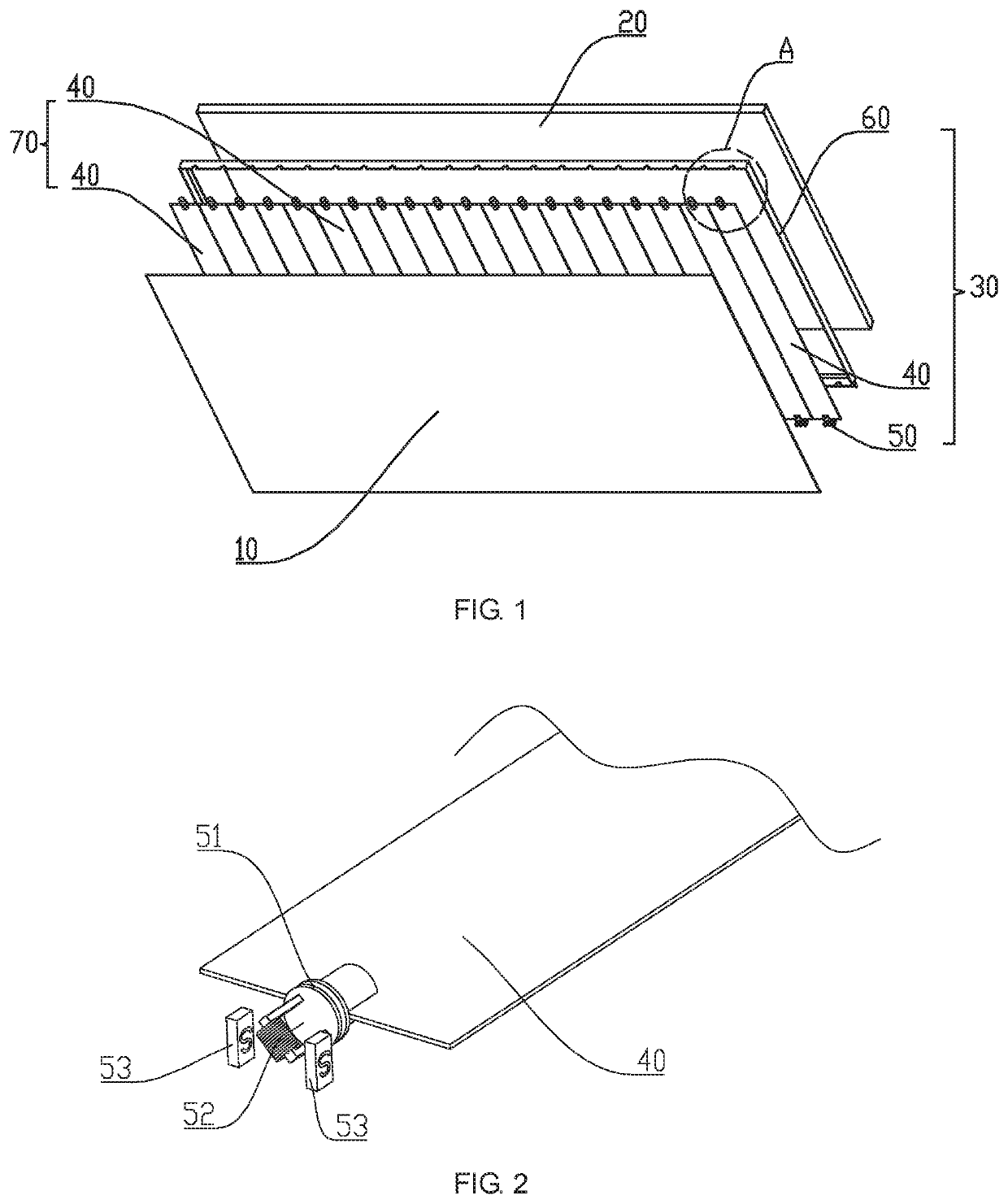
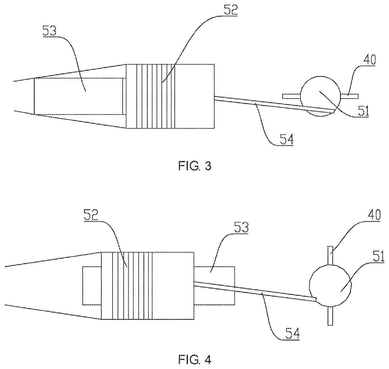
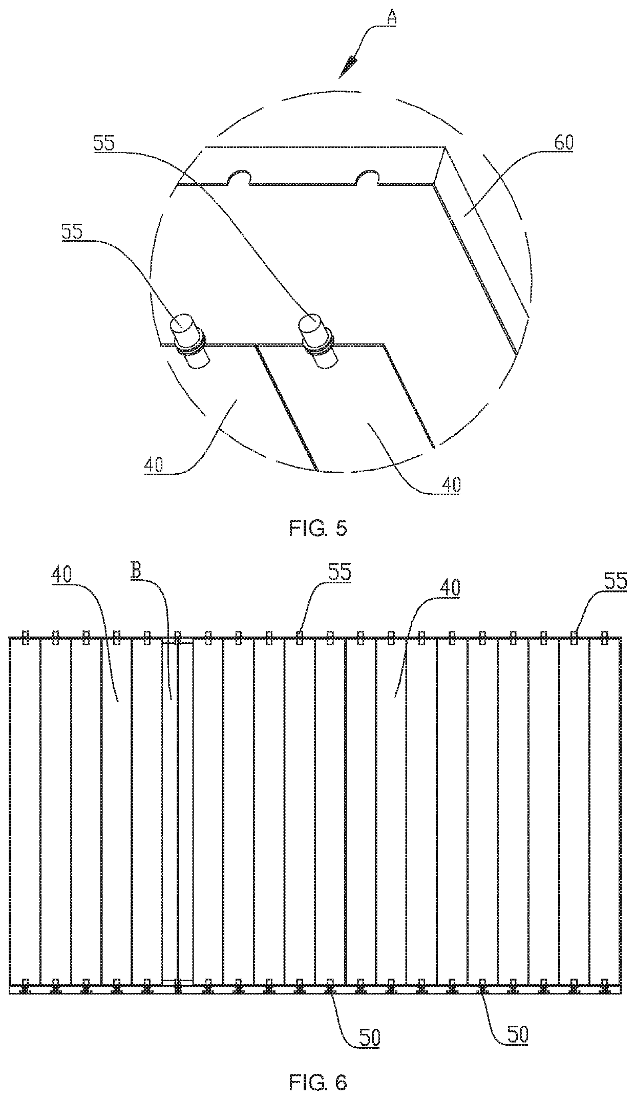
This patent is about a controllable backlight structure for liquid crystal panels that allows for individual control of the backlight source in different areas of the panel. This is achieved by using a shutter unit with multiple blades that are each connected to a rotating mechanism. The blades can be opened or closed to control the incident lights from the backlight source, resulting in improved image quality and low power consumption. This solution is simple and easy to implement, and is especially useful for high-quality display applications such as televisions.

Problems solved by technology

The backlight control scheme and the structure of the existing liquid crystal display device are complex, the power consumption is large, and the energy is not saved.
Therefore, the prior art still needs further development.

Method used


Image

  • Controllable backlight structure and display device
  • Controllable backlight structure and display device
  • Controllable backlight structure and display device

Examples


Embodiment Construction

[0030]The technical solution in the embodiments of the present disclosure will be described clearly and completely hereinafter with reference to the accompanying drawings in the embodiments of the present disclosure. Apparently, the described embodiments are merely some but not all of the embodiments of the present disclosure. All other embodiments obtained by a person of ordinary skill in the art based on the embodiments of the present disclosure without creative efforts shall fall within the protection scope of the present disclosure.

[0031]It should be noted that, all the directional indications (such as up, down, left, right, front, back . . . ) in the embodiments of the present disclosure are only used to explain the relative position relationship, the movement condition, and the like of the components in a specific posture (as shown in the drawings). If the specific gesture changes, the directivity indication also changes accordingly.

[0032]In the present disclosure, the terms “...


PUM

PropertyMeasurementUnit
magnetic fieldaaaaaaaaaa
rotation angleaaaaaaaaaa
energyaaaaaaaaaa

Abstract

The present disclosure discloses a controllable backlight structure and a display device using the structure. The controllable backlight structure includes a liquid crystal panel and a backlight source for providing a light source for the liquid crystal panel, wherein a shutter unit is disposed between the liquid crystal panel and the backlight source, the shutter unit includes a plurality of blades arranged in an array, each blade is connected with at least one rotating mechanism, the rotating mechanism is connected with a control circuit, a rotation of each rotating mechanism opens and closes one blade to control the backlight source to have different incident light in different regions of the liquid crystal panel. The structure of the controllable backlight of the present disclosure is simple and easy to implement. The structure of the controllable backlight with improved image quality of the liquid crystal is simple and easy to be implemented.

Description

RELATED APPLICATIONS[0001]The present application is a National Phase of International Application Number PCT / CN2018 / 073210, filed Jan. 18, 2018, and claims the priority of China Application No. 201711461198.3, filed Dec. 28, 2017.FIELD OF THE DISCLOSURE[0002]The present disclosure relates to a liquid crystal backlight technology field, and more particularly to a controllable backlight structure and a display device using the structure.BACKGROUND OF THE DISCLOSURE[0003]With the development of LCD TVs, LCD TV quality requirements are getting higher and higher. HDR (High-Dynamic Range) through the backlight partition control and LCD contrast to enhance the contrast of the TV screen, improve the quality.[0004]The backlight control scheme and the structure of the existing liquid crystal display device are complex, the power consumption is large, and the energy is not saved.[0005]Therefore, the prior art still needs further development.SUMMARY OF THE DISCLOSURE[0006]In view of the above ...

Claims


Application Information

Patent Timeline
Patent Type & Authority Applications(United States)
IPC IPC(8): G02F1/13357
CPCG02F2001/133601G02F1/1336G09G3/3406G09G3/36G02F1/133606G02F1/133601
Inventor LI, DEHUA
Owner HUIZHOU CHINA STAR OPTOELECTRONICS TECHNOLOGY CO LTD
Learn More