Overheating destructive switch

a technology of destructive switch and overheating, which is applied in the direction of thermal switch details, tumbler/rocker switch details, coupling device connection, etc., can solve the problems of excessive energy consumption, poor conductivity of fuse, and excessive energy consumption, so as to increase the size of the switch, the overall structure is simple and easy to manufacture, and the current transmission of the electrical appliance or the extension cord is not hampered.

Active Publication Date: 2020-06-02
GREEN IDEA TECH INC
View PDF24 Cites 0 Cited by
  • Summary
  • Abstract
  • Description
  • Claims
  • Application Information

AI Technical Summary

Benefits of technology

[0031]The following effects can be achieved according to the aforesaid technical features:
[0032]1. In comparison with the conventional protection technologies using a fuse or a bimetallic strip, the overheating destructive element of the present invention is not located in a path of current transmission and is not responsible for transmitting currents; therefore, when the present invention is applied to an electrical appliance or an extension cord, the current transmission of the electrical appliance or the extension cord will not be hampered even though the conductivity of the overheating destructive element is not as good as that of copper or is even a non-conducting insulative body.
[0033]2. The overall structure is simple and easy to manufacture without increasing a size of the switch obviously, and the production cost is relatively lower and easy to be implemented in known rocker switches, push switches or other switches.
[0034]3. The small size and low cost is suitable for applications to switches of an extension cord. For example, installing each of the power socket of the extension cord with an overheating destructive switch ensures the safety of each set of socket apertures corresponding to each of the switches when in use, and also redresses the high cost of conventional bimetallic strips, and the shortcoming thereof whereby a plurality of sets of socket apertures are required to jointly use one overload protection switch, which will not protect socket apertures distanced further away from the overload protection switch that are already overheating, resulting in an increase in temperature thereof, but the overload protection switch has still not tripped because the temperature has not yet reached the trip temperature.

Problems solved by technology

Using an extension cord as an example, in which copper is mainly used as a conducting body, if the extension cord has combined therein the switch of the R.O.C. Patent No. 321352 for controlling a power source, the conductivity of the fuse would be poor, which leads to the issue of excessive energy consumption.
Yet the bimetallic strip is dependent on currents flowing through for the overload protection to be available, and since the conductivity of the bimetallic strip is poorer than that of copper, it also leads to the issue of excessive energy consumption.
1. The metal pins of a plug are severely oxidized and the metal pins are covered by oxidized substances; when the plug is inserted into the power socket, the poorly conductive oxidized substances make the resistance greater and thus causing overheating in the power socket.
2. When the metal pins of the plug is inserted into the power socket, but the insertion is incomplete and results in only local contacts, an excessively small contact area causes overheating in the power socket.
3. The metal pins of the plug is deformed or worn out, which results in incomplete contact when the plug is inserted, and an excessively small contact area causes overheating in the power socket.
4. The metal pins of the plug or the metal members of the power socket are covered by foreign materials such as dusts or dirt, which makes the conductivity poorer and causes overheating due to increased resistance.
However, the overload protection switch employing the form of a bimetallic strip is more costly, and would result in a significant increase in price if each power socket of an extension cord is to be provided with an overload protection switch, which lead the overload protection switch to go against it being available to all.

Method used


Image

  • Overheating destructive switch
  • Overheating destructive switch
  • Overheating destructive switch

Examples


first embodiment

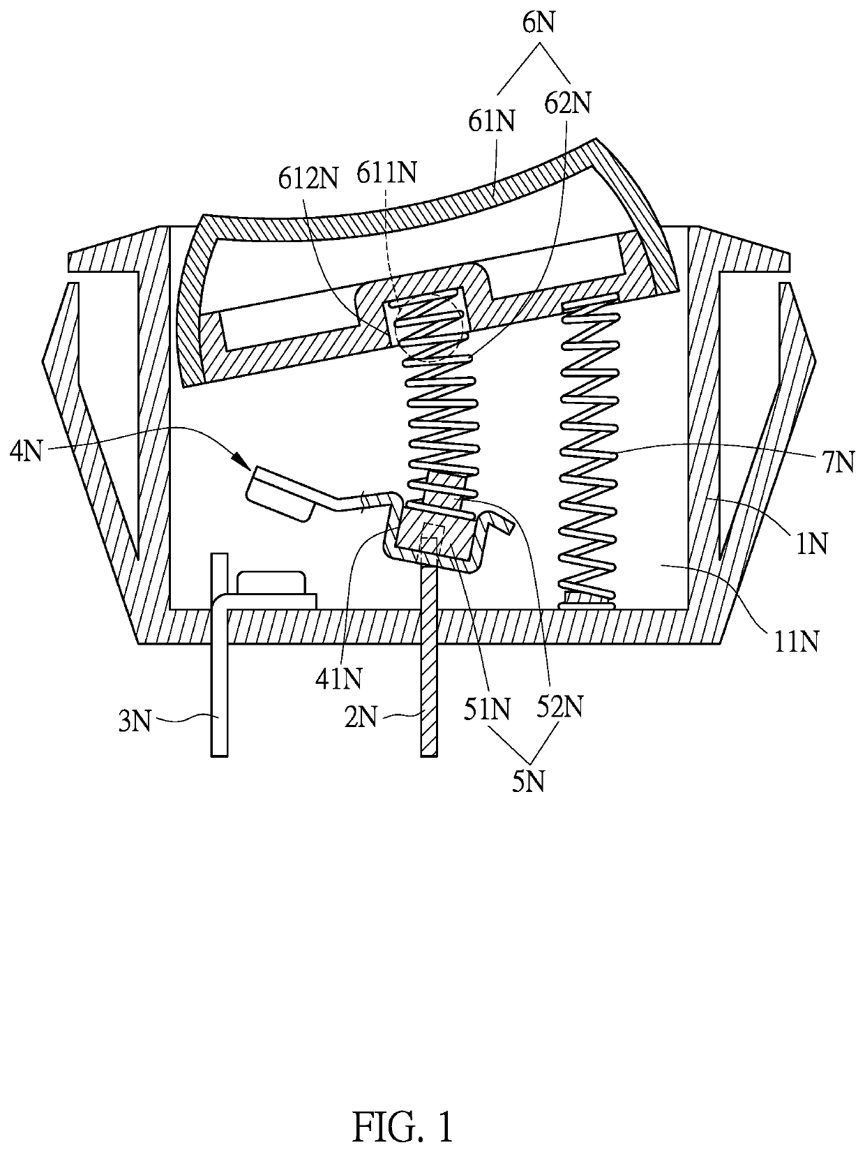
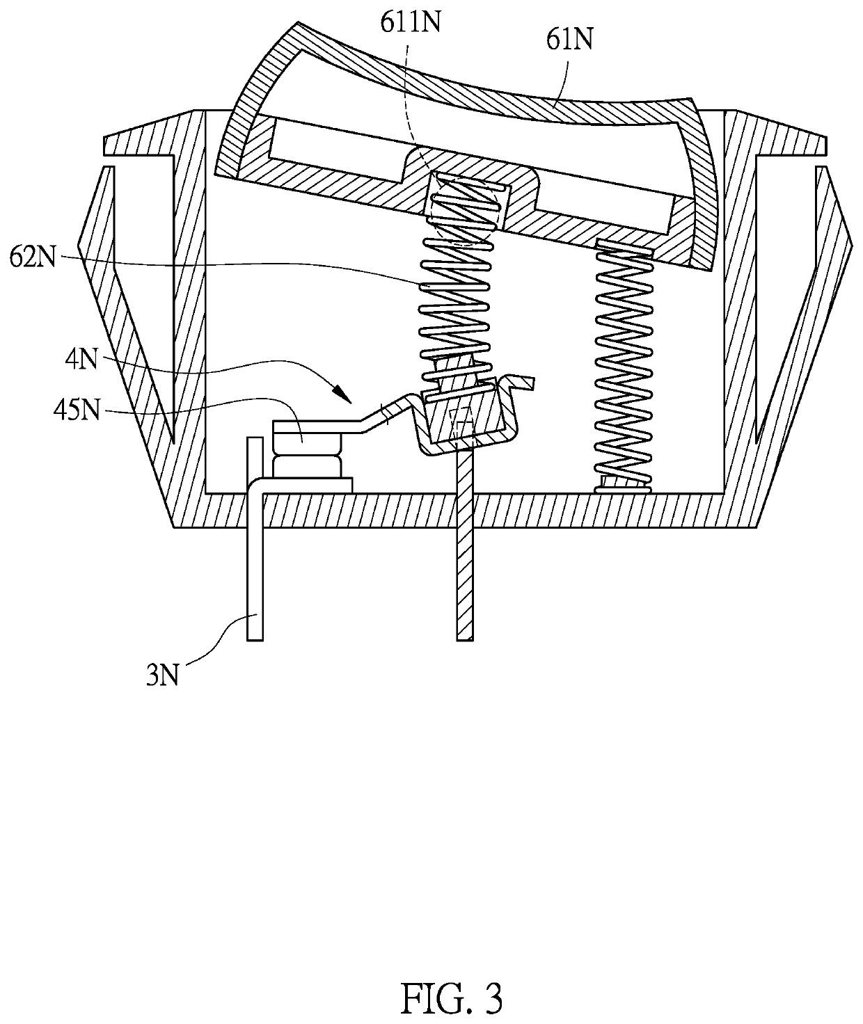
[0051]Referring to FIG. 1 for the present invention, an overheating destructive switch of the embodiment is in a form of a rocker switch, wherein FIG. 1 shows that the rocker switch is in a disconnected state.

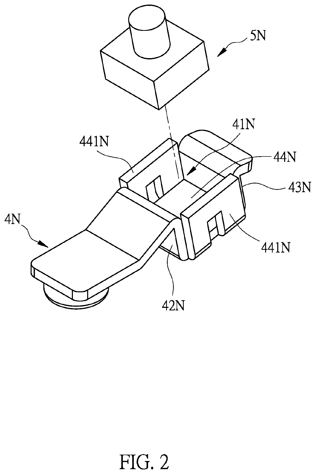
[0052]The rocker switch comprises: a base (1N) having a receiving space (11N); a first conductive element (2N) and a second conductive element (3N) penetrated into and provided in the base (1N); a movable conductive element (which can be referred to as a rocker conductive element (4N) in this embodiment) provided in the receiving space (11N); an overheating destructive element (5N); an operating component (6N) assembled on the base (1N), wherein the operating component (6N) comprises an operating element (61N) and a first elastic element (62N); and a second elastic element (7N). In which:

[0053]the rocker conductive element (4N) is provided over the first conductive element (2N) and electrically connected to the second conductive element (3N). The overheating destructive element...

fourth embodiment

[0060]Referring to FIG. 10 for the present invention, an overheating destructive switch is shown in the embodiment and is in a form of a push switch, wherein FIG. 10 shows that the push switch is in a disconnected state.

[0061]The push switch comprises:

[0062]a base (1R) having a receiving space (11R) and a protruding portion (12R); a first conductive element (2R) and a second conductive element (3R) penetrated into and provided in the base (1R); a movable conductive element provided in the receiving space (11R), wherein the movable conductive element is a conductive cantilever element (4R); an overheating destructive element (5R) which can be destroyed at a destructive temperature, wherein the destructive temperature is between 100° C. to 250° C. The overheating destructive element (5R) is not used to maintain the continuous supply of currents, and thus can be selectively made of an insulative material such as a plastic but is not limited thereto, and can also be selected from a non-...


PUM


Abstract

An overheating destructive switch, comprising: a first conductive element, a second conductive element, a movable conductive element, an overheating destructive element, an operating component, and a second elastic element. The movable conductive element connects the first conductive element and the second conductive element. A first elastic element and the second elastic element act on an operating element. The first elastic element is compressed and has a first elastic force, and the second elastic element has a second elastic force. The first elastic force is greater than the second elastic force under in a normal state. When the overheating destructive element is destroyed due to overheating, the first elastic force is reduced or lost, such that the second elastic force becomes greater than the first elastic force. The movable conductive element is consequently disconnected from the first conductive element and the second conductive element, thus achieving protection against overheating.

Description

CROSS REFERENCES TO RELATED APPLICATIONS[0001]The present application claims priority from Taiwanese Patent Application Serial Number 107123018, filed Jul. 3, 2018, the disclosure of which is hereby incorporated by reference herein in its entirety.BACKGROUND OF THE INVENTION(a) Field of the Invention[0002]The present invention relates to an overheating destructive switch and, more particularly, to an electrical disconnection structure which differs from a fuse and a bimetallic strip. An overheating destructive element of the present invention is not dependent on currents flowing through for destruction, but carries out destruction by means of heat energy transmission so as to electrically disconnect the switch.(b) Description of the Prior Art[0003]A rocker switch of the prior art controls a switch to move reciprocally and pivotally within a certain angular range so as to control the switch to be connected or disconnected; for instance, in R.O.C. Patent No. 560690 which is entitled “...

Claims


Application Information

Patent Timeline
Patent Type & Authority Patents(United States)
IPC IPC(8): H01R13/713H01H3/02H01H3/12H01H3/54H01H1/24H01R25/00
CPCH01H3/54H01H3/12H01R13/7137H01H3/022H01H2221/016H01H2239/06H01H2221/044H01H2221/068H01H1/24H01R25/003H01H13/02H01H23/02H01H37/32H01H2203/056H01H23/205H01H37/043H01H85/08
Inventor I, HSIANG-YUN
Owner GREEN IDEA TECH INC
Why Eureka
Try Eureka