
Ophthalmic system including accommodating intraocular lens and remote component and related methods of use

a technology of ophthalmic systems and remote components, applied in the field of ophthalmic systems, can solve the problems of reducing the cost and burden of patients, and reducing the flexibility of implantable accommodating lenses

Active Publication Date: 2020-05-07
VERILY LIFE SCI LLC
View PDF0 Cites 2 Cited by
  • Summary
  • Abstract
  • Description
  • Claims
  • Application Information

AI Technical Summary

Benefits of technology

The patent describes an ophthalmic system that includes an accommodating intraocular device and a remote component. The system uses dynamic optical power to provide accommodation for patients with cataracts and presbyopia. The system includes a power source to change the optical power of the accommodating intraocular device. The patent also describes various methods for controlling the optical power of the system. The technical effects of the patent include improved vision for patients with cataracts and presbyopia through the use of an accommodating intraocular device, as well as reduced burden and cost associated with replacing the implantable lens.

Problems solved by technology

Implanted batteries and other conventional implantable power sources may fail over time, requiring replacement of the implantable lens; a process that may be costly and burdensome to patients.
Further, batteries in implantable accommodating lenses add bulk and reduce flexibility of implantable accommodating lenses generally leading to more invasive implantation and removal procedures.

Method used


Image

  • Ophthalmic system including accommodating intraocular lens and remote component and related methods of use
  • Ophthalmic system including accommodating intraocular lens and remote component and related methods of use
  • Ophthalmic system including accommodating intraocular lens and remote component and related methods of use

Examples


Embodiment Construction

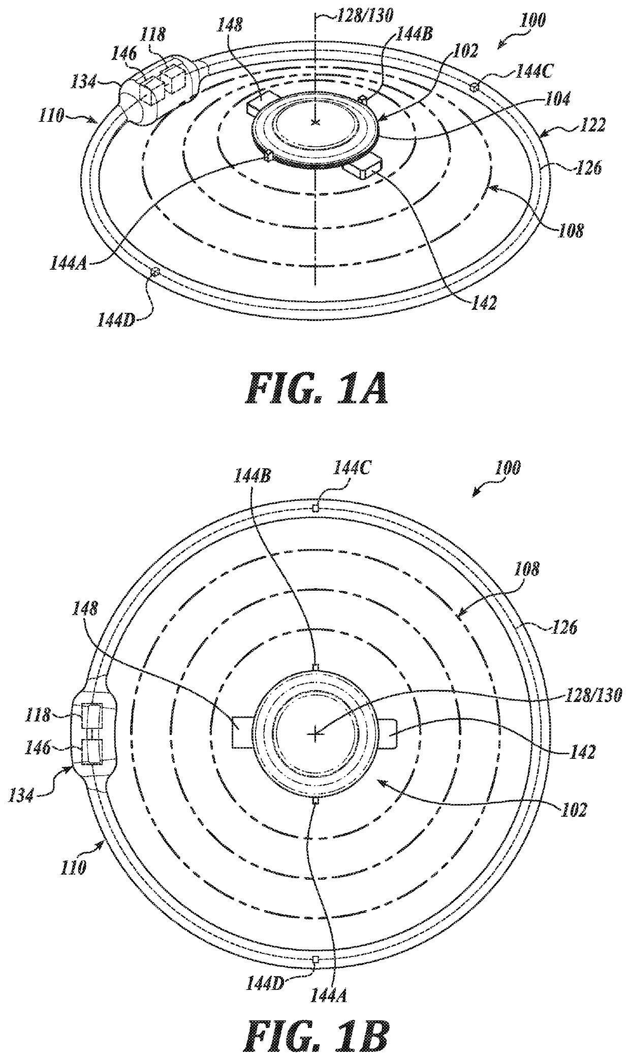
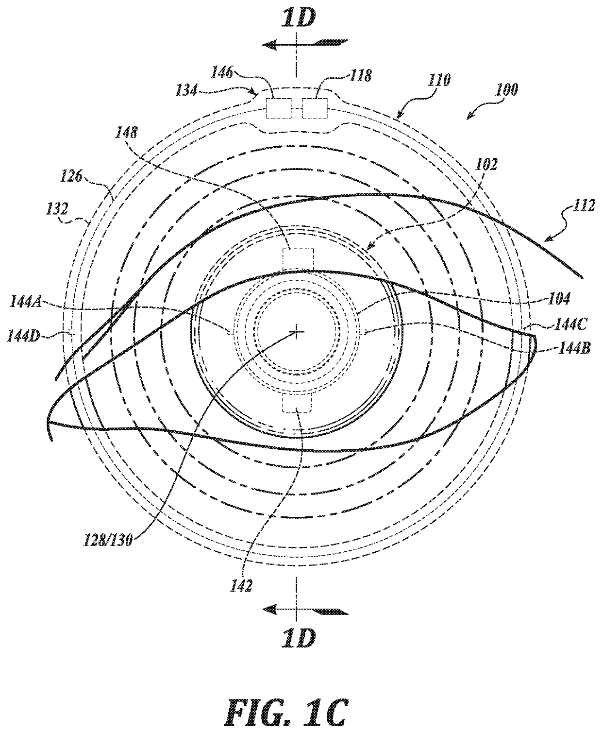
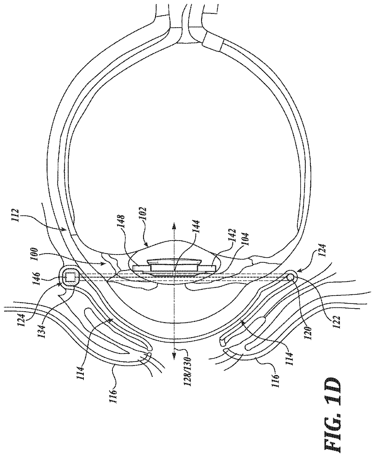
[0018]Embodiments of an accommodating ophthalmic system including an accommodating intraocular device and a remote component and related methods of use are described herein. In the following description numerous specific details are set forth to provide a thorough understanding of the embodiments. One skilled in the relevant art will recognize, however, that the techniques described herein can be practiced without one or more of the specific details, or with other methods, components, materials, etc. In other instances, well-known structures, materials, or operations are not shown or described in detail to avoid obscuring certain aspects.

[0019]Reference throughout this specification to “one embodiment” or “an embodiment” means that a particular feature, structure, or characteristic described in connection with the embodiment is included in at least one embodiment of the present invention. Thus, the appearances of the phrases “in one embodiment” or “in an embodiment” in various place...


PUM


Abstract

Ophthalmic systems and methods of changing an optical power of an ophthalmic system are described. In an example, the ophthalmic system includes an accommodating intraocular device shaped to be implantable in an eye and an extraocular device separate from the accommodating intraocular device shaped to be removably mountable to a portion of the eye outside a bulb of the eye, such as an underlid portion of the eye. In an example, the method includes wirelessly transmitting power from a power source of an extraocular device removably mounted outside a bulb of an eye to an accommodating intraocular device implanted in the eye. In an example, the method includes sensing with an accommodation sensor biological accommodation signals of the eye; generating accommodation control signals representative of the biological accommodation signals; and driving an accommodation actuator disposed in the accommodating intraocular device based on the accommodation control signals to change an optical power of the ophthalmic system.

Description

CROSS-REFERENCE TO RELATED APPLICATION[0001]This application claims the benefit of U.S. Provisional Application No. 62 / 755,772, filed Nov. 5, 2018, which is hereby incorporated by reference in its entirety.TECHNICAL FIELD[0002]This disclosure relates generally to ophthalmic systems and, in particular but not exclusively, relates to accommodating ophthalmic systems.BACKGROUND INFORMATION[0003]Cataracts and presbyopia may be treated with implantable lenses that provide accommodation. Cataract treatment includes implantation of a replacement lens. Such lenses, which may also be referred to as intraocular lenses, may provide static accommodation, dynamic accommodation, or a combination thereof. Various techniques may be available to provide dynamic accommodation, such as mechanically or electrically controlled accommodation. The accommodation may be provided by actuation of a dynamic optical component that provides multiple levels of optical power. The change in optical power may provid...

Claims


Application Information

Patent Timeline
IPC IPC(8): A61F2/16
CPCA61F2250/0001A61F2/1624A61F2230/0065
Inventor GUTIERREZ, CHRISTIANBASINGER, BROOKEJOHNSON, PATRICIAKUIPER, STEINSHAH, KEDARGOETZ, GEORGESNAGESH, SHISHIRAGORDON, CHELSEA
Owner VERILY LIFE SCI LLC
Learn More