Clamping device with excavation function

Inactive Publication Date: 2020-05-07
HOMAG GMBH
View PDF0 Cites 0 Cited by
  • Summary
  • Abstract
  • Description
  • Claims
  • Application Information

AI Technical Summary

Benefits of technology

[0064]In this way, it is possible to provide a compact, stand-alone clamping device which can be changed quickly and easily, as already mentioned above. Changed is to be understood here to mean that a clamping device attached to a machine table can be easily released, wherein a preferred mechan

Problems solved by technology

With this device it is not possible to grip the received workpieces such that they can be manipulated.
During the necessary milling work, high chip-removal forces occur, which can lead to the component being subject to considerable strain and deformations.
The two clamping devices described above cannot meet these requirements since they offer too little rigidity and therefore the machining quality (tolerance c

Method used


Image

  • Clamping device with excavation function
  • Clamping device with excavation function
  • Clamping device with excavation function

Examples


Embodiment Construction

[0075]In the following, preferred embodiments of the present invention will be described in detail on the basis of the enclosed drawings. Further modifications cited in this context of certain features can each individually be combined in order to form new embodiments.

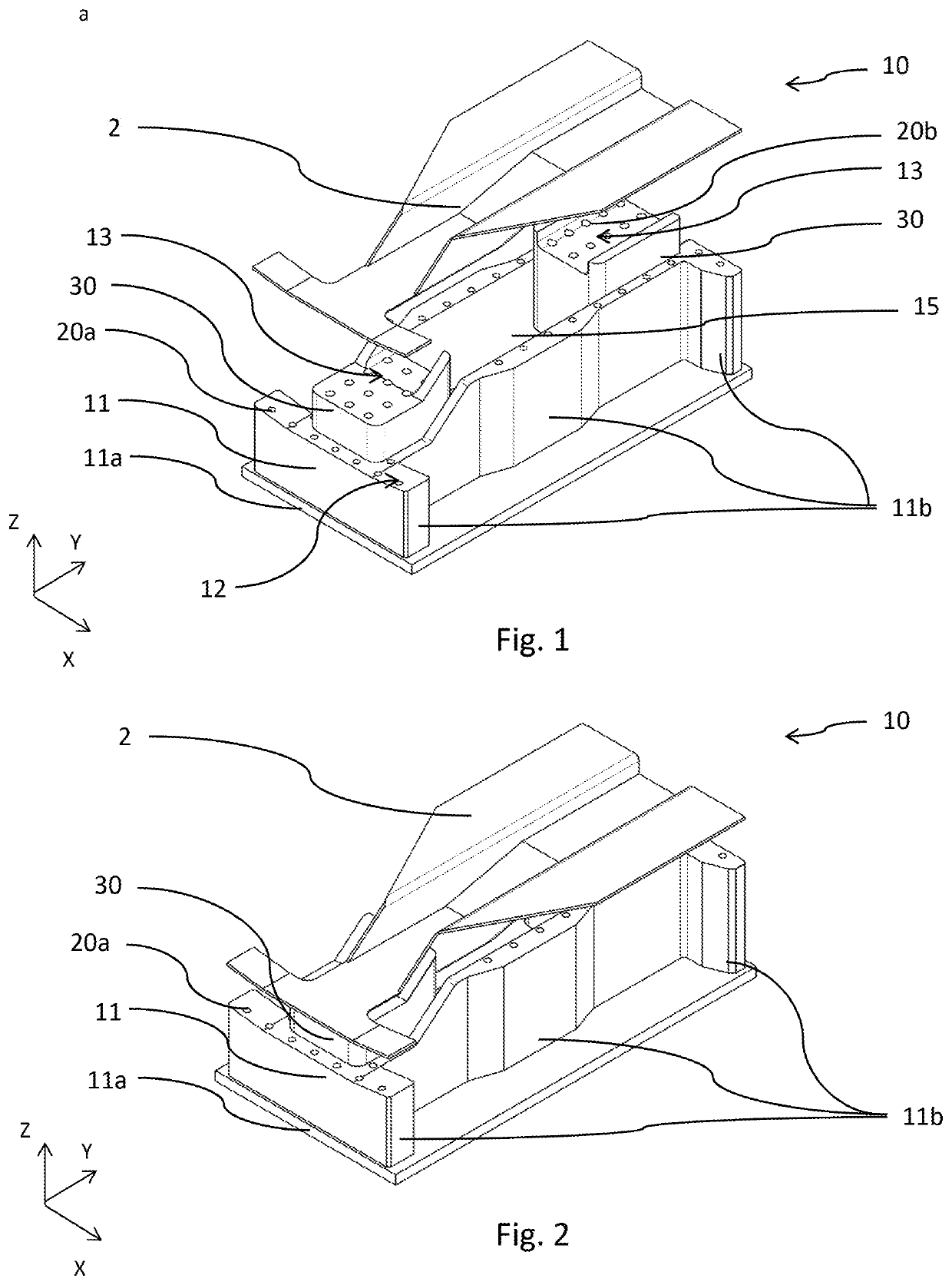
[0076]FIG. 1 shows a clamping device 10 comprising a base body 11. Within the scope of the preferred embodiment described, this is a clamping device 10 for receiving a workpiece 2 consisting of fiber composite material which has, for example, a U-shaped profile form as shown in FIG. 1. A first receiving section 12 is formed on the base body 11 which serves to facilitate the attachment of the clamping device 10 to a machine table (not shown) of a machining device. As can also be derived from FIG. 1, the first receiving section 12 faces the workpiece 2 to be received. For the sake of clarity the workpiece 2 is shown above the clamping device 10, i.e. in a state not yet received by the clamping device 10. Moreover, also f...


PUM


Abstract

The present invention relates to a clamping device (10) and a method for clamping a workpiece (2), preferably to a machining device, in particular for clamping a workpiece (2) having one or more curved surfaces or free-form surfaces, comprising: a first receiving section (12) for receiving a workpiece (2), which preferably has at least in sections thereof a first negative form relative to the workpiece (2) to be received, a second receiving section (13) for receiving the workpiece (2), which preferably has at least in sections thereof a second negative form relative to the workpiece (2) to be received, wherein one of the receiving sections (12, 13) can be moved out of a first position relative to the other receiving section (12, 13) into a second position, and one or more clamping mechanisms (20a, 20b) is/are provided on the first receiving section (12) and/or on the second receiving section (13).

Description

TECHNICAL FIELD[0001]The present invention relates to a clamping device for a machining device, in particular for clamping a workpiece having one or more curved surfaces or free-form surfaces and preferably consisting of, for example, a composite material such as fiber composite material, wood, wood-based materials or similar. Moreover, the present invention relates to a method for clamping a workpiece having one or more free-form surfaces, in particular using the clamping device according to the invention.[0002]The device and the method according to the present invention are used in particular in the field of machining light-weight components, and in particular for machining fiber composite components on CNC machining devices. The aforementioned workpieces (light-weight components) are preferably 3D components such as car body panels, trim parts, structural components or furniture parts.PRIOR ART[0003]One example of a known receiving device for a workpiece having one or more free-f...

Claims


Application Information

Patent Timeline
IPC IPC(8): B25B11/00B23Q1/03B23Q3/06B23Q3/08
CPCB25B11/005B23Q1/035B23Q2703/04B23Q3/062B23Q3/088
Inventor GRINGEL, MARTINDOLL, BERNHARD
Owner HOMAG GMBH
Why Eureka
Try Eureka