Improved dental implant system

Pending Publication Date: 2020-05-14
STRAUMANN HLDG AG
View PDF0 Cites 3 Cited by
  • Summary
  • Abstract
  • Description
  • Claims
  • Application Information

AI Technical Summary

Benefits of technology

The present invention provides an improved dental implant system that overcomes the shortcomings of previous dental implants. The dental implant and secondary part are securely connected in multiple angular positions, and the system has enhanced mechanical strength and torsional resistance. Additionally, the manufacturing process of the dental implant is simplified, reducing production costs. The coupling between the dental implant and secondary part, which was previously cumbersome and required multiple parts, is now optimized. Furthermore, the number of parts in the dental implant system is minimized.

Problems solved by technology

A frequent problem arising with the above-described multi-part dental implant systems is the difficulty of correct angular positioning and stability of the abutment or of the secondary part within the dental implant which has already been placed in the bone tissue.
Further, as the same coupling means are used to position the secondary part on the dental implant and to couple the same to an insertion instrument which is used to place the dental implant in the bone tissue, the problem of sufficient torque resistance of the coupling means arises.
Yet another problem arising in multi-part dental implant systems is the sealing between the dental implant and the secondary part, as for the sake of sterility, the penetration of fluid into the internal blind bore of the dental implant via the coupling means should be minimized.

Method used


Image

  • Improved dental implant system
  • Improved dental implant system
  • Improved dental implant system

Examples


Embodiment Construction

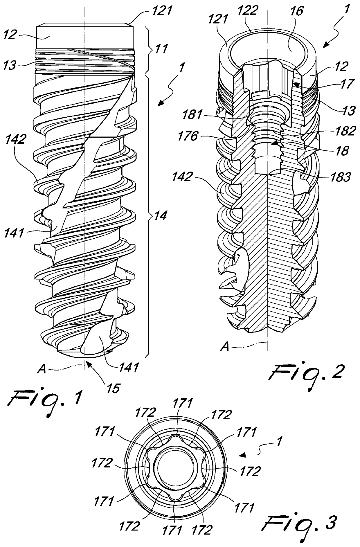
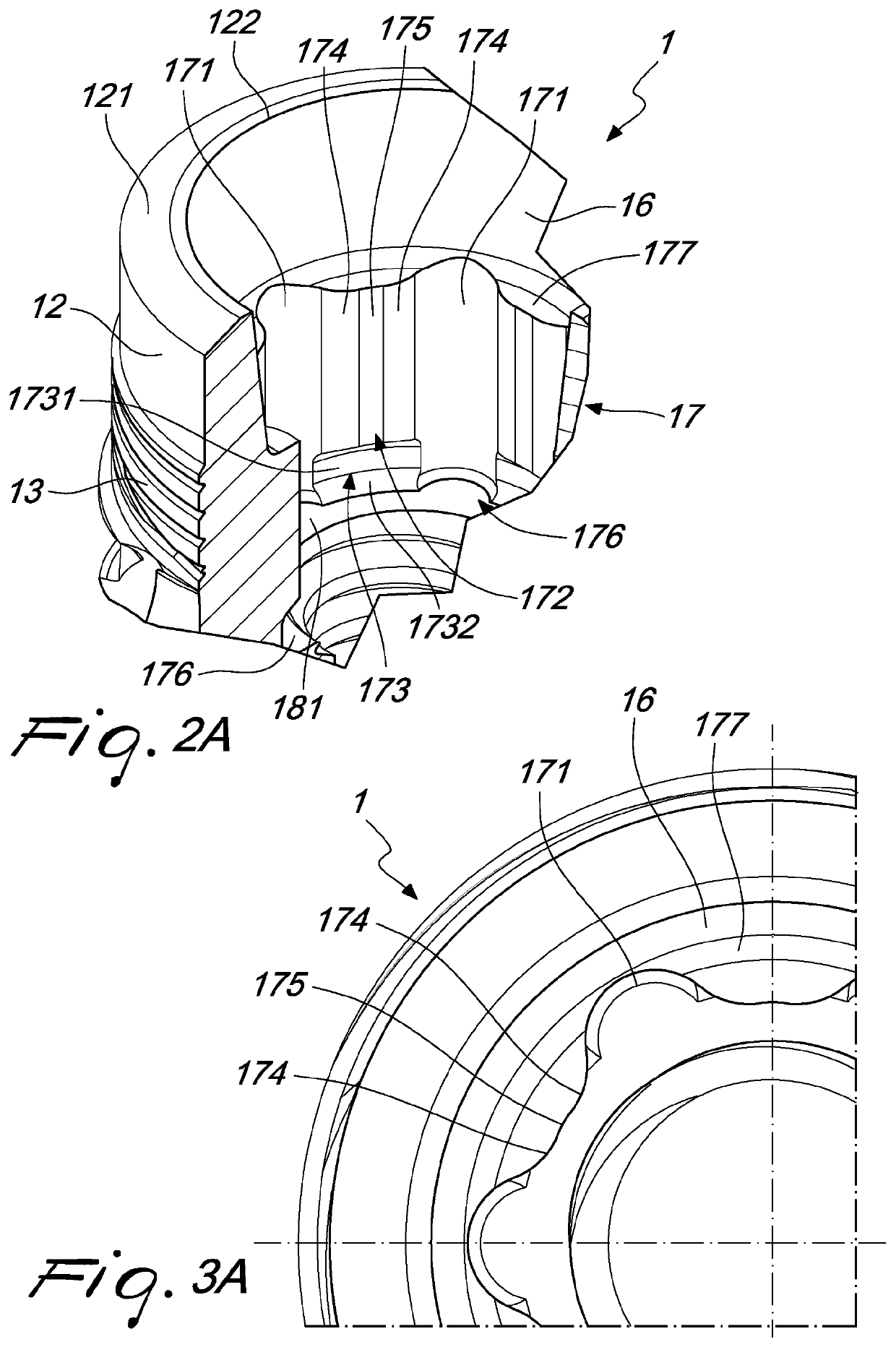
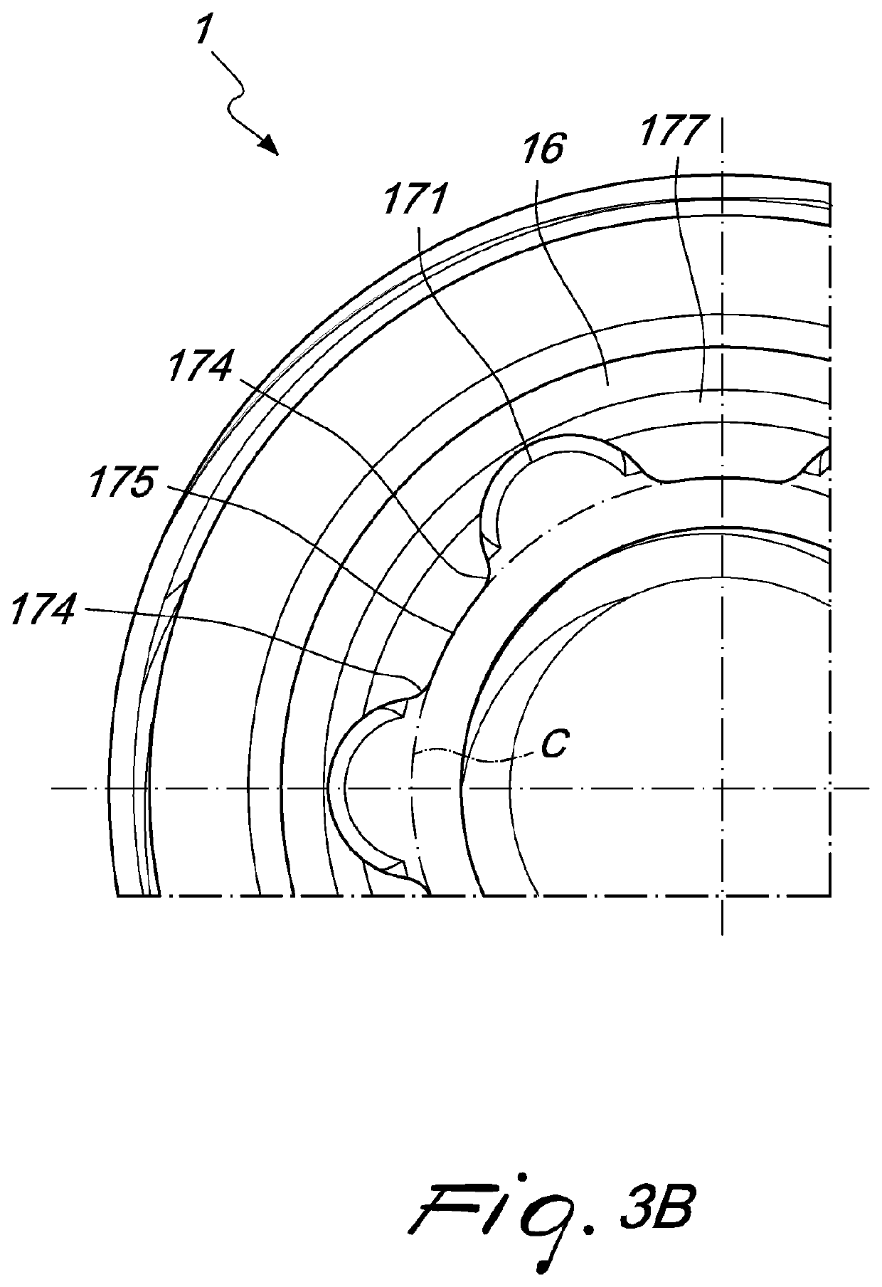
[0085]Whenever reference is made in the present specification to connecting lobes or to linking areas as having a concave or a convex shape, such concavity or convexity is understood as referring to a transverse cross section of a dental implant, a secondary part, an insertion tool, a healing cap along a plane that is perpendicular to a longitudinal axis of the listed dental items.

[0086]With reference to the enclosed FIG. 1 reference numeral 1 designates a dental implant, in particular a dental implant screw, having a coronal section 11 and a threaded region 14 extending apically from the coronal section 11 to an apical tip 15 of the dental implant 1. The coronal section 11 includes at an external part thereof a smooth section 12 extending in the apical direction from the coronal end of the dental implant 1 and a threaded section 13 extending in the apical direction from the apical end of the smooth section 12 up to a coronal end of the threaded region 14. The dental implant 1 has a...


PUM


Abstract

A dental implant having a substantially cylindrical shape with a longitudinal axis defining a longitudinal direction, including: a coronal section including a coronal end of the implant; a threaded region extending apically from the coronal section to an apical tip of the implant; and an internal blind bore for connection to a secondary part, including: a stabilizing section extending apically from the coronal end; and a drive and indexing section which extends apically from an apical end of the stabilizing section, which includes a plurality of connecting lobes having a concave shape and extending in the longitudinal direction, being interconnected by respective lobe linking areas, including: two convex sections extending in the longitudinal direction and adjacent to a respective connecting lobe; and a concave section extending in the longitudinal direction between the two convex sections. Further, a secondary part and an insertion tool of a configuration matching the dental implant.

Description

FIELD OF THE INVENTION[0001]The present invention relates in general to a dental implant with an improved coupling for an insertion tool and / or for a secondary part and / or any other superimposed element, such as, for instance, an abutment, superimposed on the dental implant. The present invention also relates to a secondary part, such as, for instance, an abutment, with an improved coupling to a dental implant. Moreover, the present invention also relates to an insertion tool with an improved coupling to a dental implant. In addition, the present invention also relates to a dental implant system, in particular a multi-part dental implant system with an improved coupling between a dental implant and a secondary part, such as, for instance, an abutment, wherein the coupling is also suitable for cooperating with an insertion tool intended to place the dental implant in a receiving bone.BACKGROUND OF THE INVENTION[0002]Generally, multi-part dental implant systems are used in dental surg...

Claims


Application Information

Patent Timeline
IPC IPC(8): A61C8/00
CPCA61C8/0066A61C8/0054A61C8/0037A61C8/0068A61C8/0089A61C8/0022A61C8/0024A61C8/005A61C8/0069A61C8/0059A61C8/008A61C8/0025
Inventor FROMOVICH, OPHIR
Owner STRAUMANN HLDG AG
Why Eureka
Try Eureka