
Rotor for a synchronous drive motor

a synchronous drive and rotor technology, applied in the direction of magnetic circuit rotating parts, electric propulsion mounting, magnetic circuit shape/form/construction, etc., can solve the problems of reducing efficiency, deformation of the rotor, and usually not being able to punch bars, so as to minimize the flux harmonic and flux leakage, and maximize the synchronous and reluctance moments.

Active Publication Date: 2020-05-14
BRUSA ELECTRONICS AG
View PDF0 Cites 0 Cited by
  • Summary
  • Abstract
  • Description
  • Claims
  • Application Information

AI Technical Summary

Benefits of technology

The technical effect of this patent is to make a rotor for a synchronous drive motor that can maximize both the synchronous and reluctance moments, while minimizing harmonics and leakage flux.

Problems solved by technology

Leakage losses, which reduce the efficiency, result primarily along the radially outer edge of the rotor via the bars between the outer circumference and the respective radially outermost cavity.
However, due to the high centrifugal forces acting on the magnets in the cavities, a deformation of the rotor would occur if the outer bars were too narrow, which would then necessitate wider bars.
From a production standpoint, it is usually not possible to punch bars that are narrower than the sheet thickness.
In any case, the edge cavities should not be populated with permanent magnets because this would result in an excessive load of the outer bars due to centrifugal forces such that the outer bars would have to be wider which, in turn, would thereby cause leakage currents.

Method used


Image

  • Rotor for a synchronous drive motor
  • Rotor for a synchronous drive motor
  • Rotor for a synchronous drive motor

Examples


Embodiment Construction

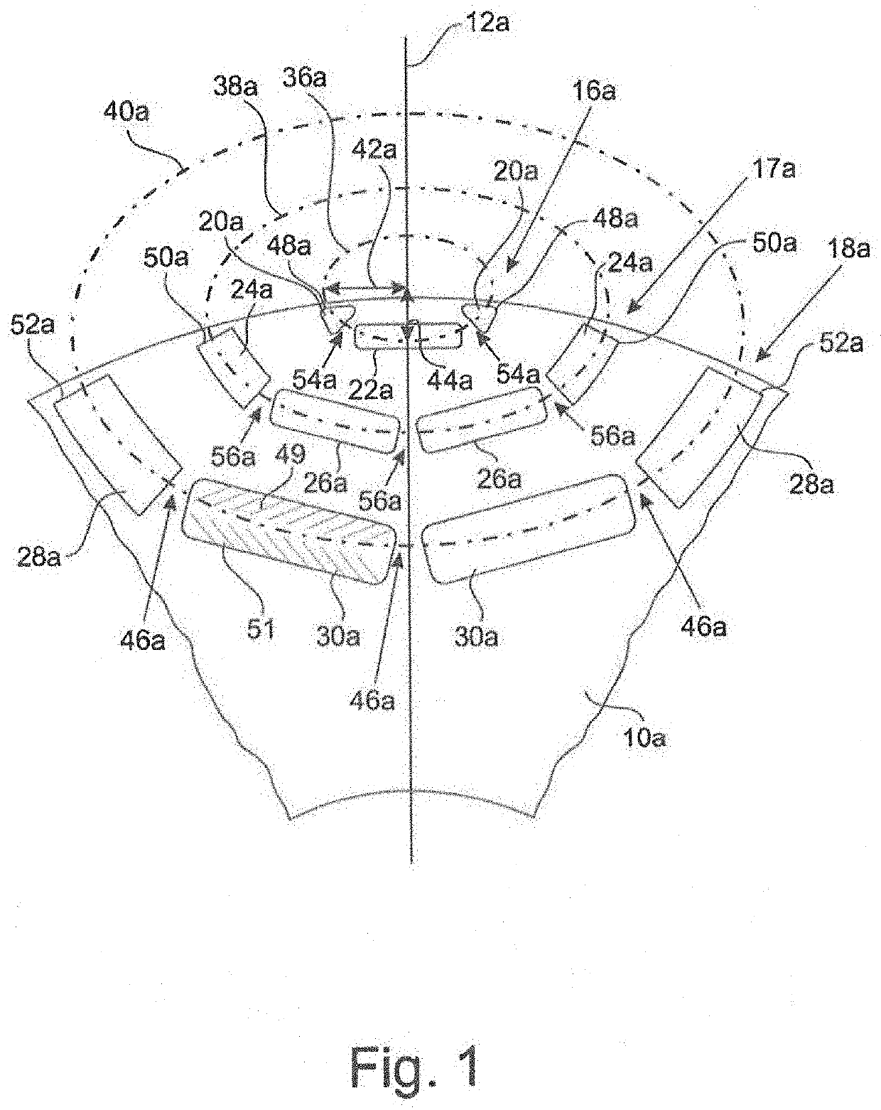
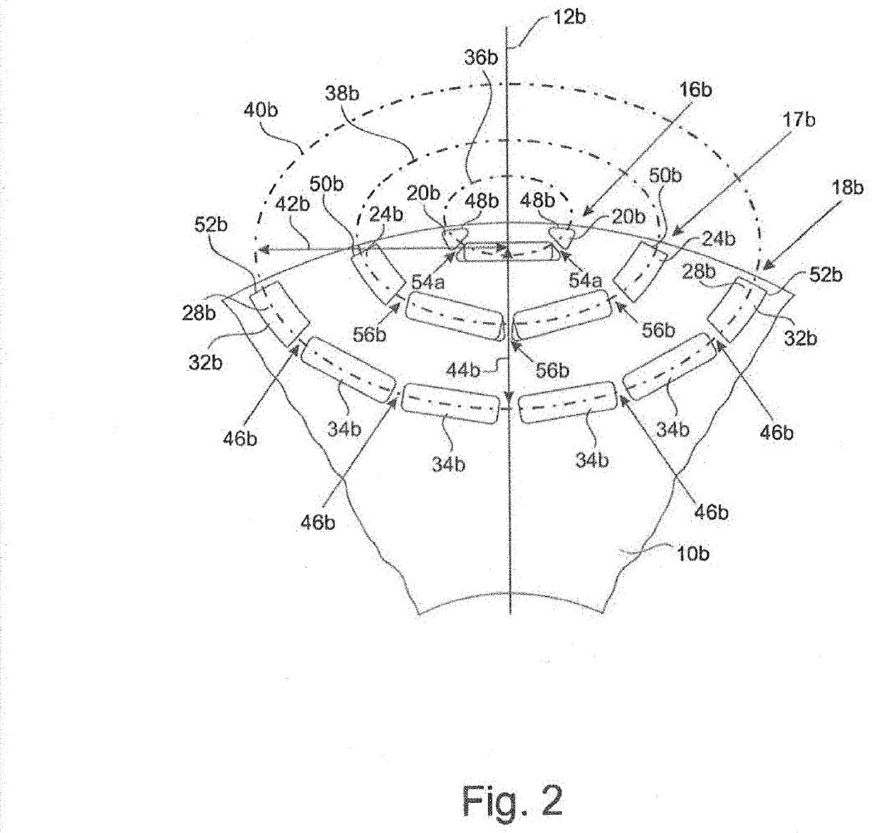
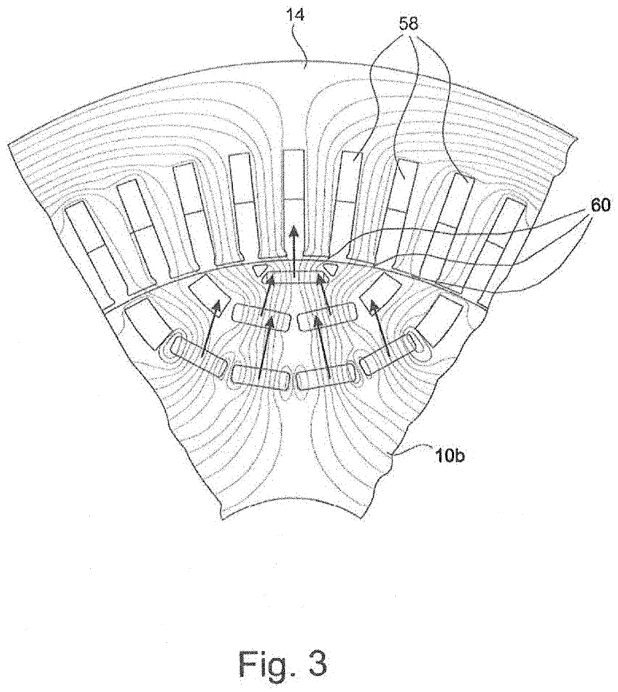
[0034]The two figures, FIGS. 1 and 2, show two embodiments of rotors 10a, 10b in the environment of a polar axis 12a, 12b. Normally, one rotor 10a, 10b has 6 to 10 poles, which are evenly distributed about the circumference. Radially outside of the rotor 10a, 10b, the rotor is surrounded by a stator 14, as sectionally shown in FIG. 3.

[0035]Each pole of a rotor 10a, 10b has three magnetic layers 16a, 16b, 17a, 17b, 18a, 18b, each including a row of cavities. Thus, in FIG. 1, the radially outermost magnetic layer 16a includes the three cavities 20a, 22a, 20a; the middle magnetic layer 17a includes the four cavities 24a, 26a, 26a, 26a, 24a; and the innermost magnetic layer 18a includes the four cavities 28a, 30a, 30a, 28a.

[0036]It is similar in FIG. 2 with the only difference that the innermost magnetic layer 18b includes six instead of four cavities, namely 32b, 34b, 34b, 34b, 34b, 32b. However, other numbers of cavities may be provided, e.g., five in the third magnetic layer 18b.

[0...


PUM


Abstract

The invention relates to a rotor for a synchronous drive motor of an electrically driven motor vehicle having several rotor poles, wherein each rotor pole has at least three magnetic layers arranged radially one after the other with cavities, wherein an outermost magnetic layer includes at least one cavity filled with permanent magnetic material and each further magnetic layer includes at least two cavities filled with permanent magnetic material, furthermore each magnetic layer has an extension of a section of an ellipse, furthermore the central points of all ellipses lie within the smallest ellipse of the outer magnetic layer, wherein each cavity belonging to one of the at least three magnetic layers defines an interface in a radial plane, and each of these interfaces of a magnetic layer of the corresponding ellipse is divided into two partial interfaces, wherein bars made of the rotor material are formed in the second and every other magnetic layer between the cavities, and these bars, at the narrowest point, are at least twice as wide as the respective outer bars of the same magnetic layer.

Description

CROSS-REFERENCE TO RELATED APPLICATIONS[0001]The present application claims priority to German Patent Application No. 10 2018 128 146.3, filed on 9 Nov. 2018, the entire contents of which are incorporated herein by reference.BACKGROUNDField[0002]The invention relates to a rotor for a synchronous drive motor of an electrically driven motor vehicle having several rotor poles, wherein each rotor pole has at least three U-shaped magnetic layers arranged sequentially, and each magnetic layer includes a row of at least three cavities, of which at least the inner cavities are filled with permanent magnetic material and furthermore the two outer cavities terminate at a rotor gap formed toward a stator, each with an outer bar. The invention further relates to a thusly equipped synchronous drive motor, as well as a motor vehicle equipped with such a drive motor.Related Art[0003]Synchronous drive motors are frequently used as a driving engine for electric vehicles, because they have a high tor...

Claims


Application Information

Patent Timeline
IPC IPC(8): H02K1/27B60K1/00
CPCH02K1/2766H02K2213/03B60K1/00H02K21/14
Inventor ZHOU, TIANOESCHGER, DANIELTEUFEL, RAPHAELMUNTEAN, ADINA
Owner BRUSA ELECTRONICS AG
Learn More