Thickness adjustment and stabilizer bar system for a case erector

a stabilizer bar and thickness adjustment technology, applied in the field of case erectors, can solve the problems of significant time and skill required to prepare the machine, and achieve the effect of improving the stabilizer

Active Publication Date: 2006-11-07
WESTERN PACKAGING SYST +1
View PDF12 Cites 29 Cited by
  • Summary
  • Abstract
  • Description
  • Claims
  • Application Information

AI Technical Summary

Benefits of technology

[0008]It is a further object of the present invention to provide a simplified and easier operated adjustment system for accommodating knocked down cases of different thicknesses.
[0013]Broadly the present invention also relates to a case forming machine for erecting cases from knock down case form to an open form and move an opened case downward to a bottom forming station comprising a fixed jaw and a moveable jaw mounted for movement on a pivotal axis between a pick-up position wherein said fixed and moveable jaws are substantially parallel and an open squaring position wherein said fixed and moveable jaws are substantially perpendicular, the improvement comprising an adjustment mechanism having a mounting portion and an adjustment portion, said mounting portion mounted for pivotal movement on said pivotal axis and said adjustment portion being moveable relative to said mounting portion in a direction substantially parallel to said fixed jaw when said moveable jaw is in said open squaring position and means to move said adjusting portion relative to said mounting portion thereby adjusting the gap between said fixed and moveable jaws when said jaws are in said parallel pick-up position.
[0015]Preferably a stop damper mounted in a fixed position relative to the fixed jaw dampens movement of said moveable jaw as it approaches said open perpendicular position and stops said moveable jaw in said open perpendicular position.
[0016]Preferably a second stop damper mounted in a fixed position relative to the fixed jaw dampens movement of said moveable jaw as it approaches said parallel pick-up position and stops said moveable jaw in said parallel pick-up position.

Problems solved by technology

These procedures required a significant amount of time and skill to ready the machine to process blanks of the new (different) thickness.

Method used


Image

  • Thickness adjustment and stabilizer bar system for a case erector
  • Thickness adjustment and stabilizer bar system for a case erector
  • Thickness adjustment and stabilizer bar system for a case erector

Examples


Embodiment Construction

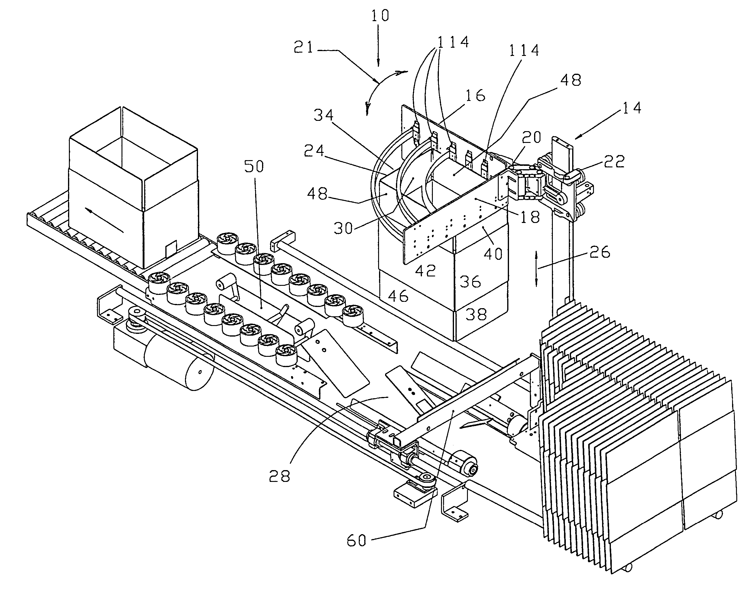
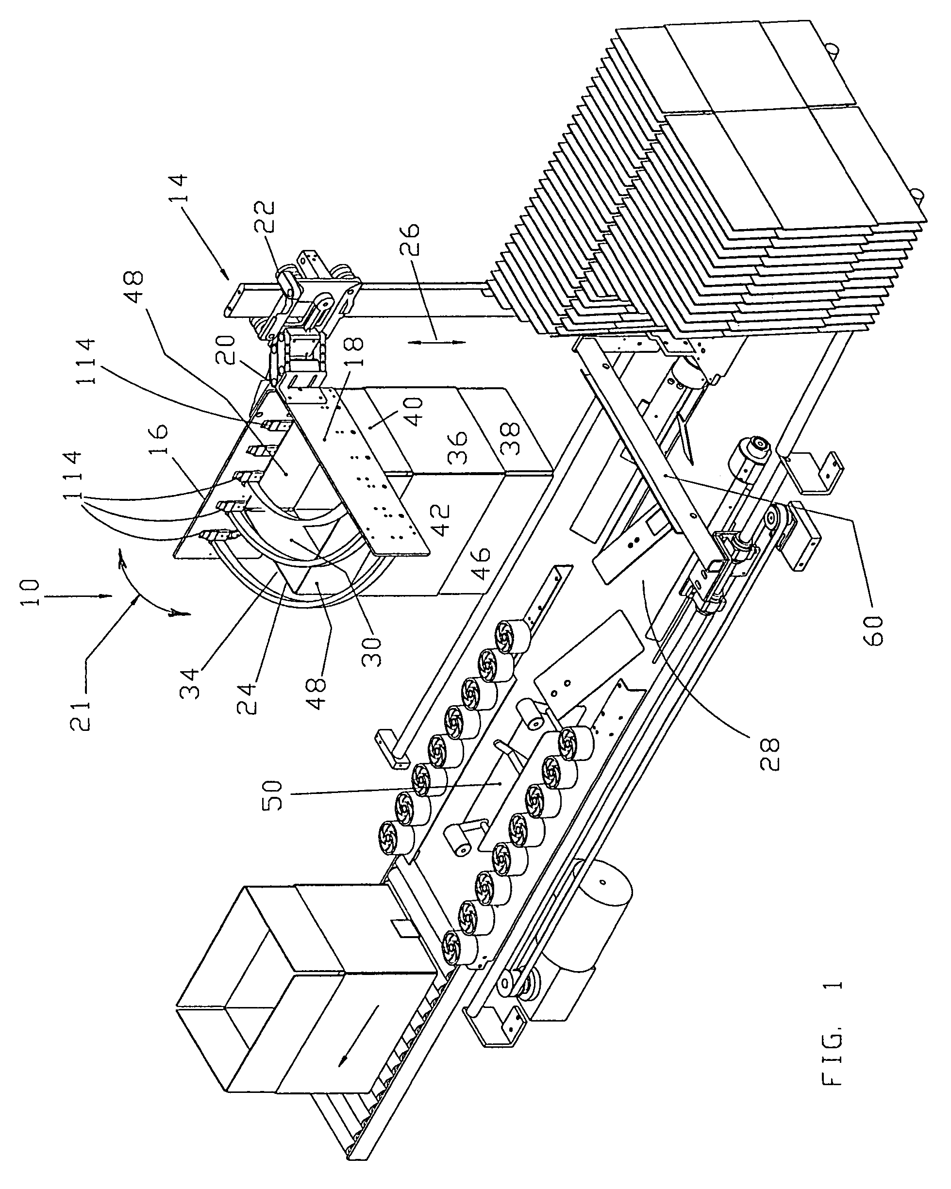
[0024]FIG. 1 illustrates a typical application of the present invention and particularly showing the invention applied to an erector of type described in U.S. Pat. No. 4,553,954 referred to above and incorporated herein by reference.

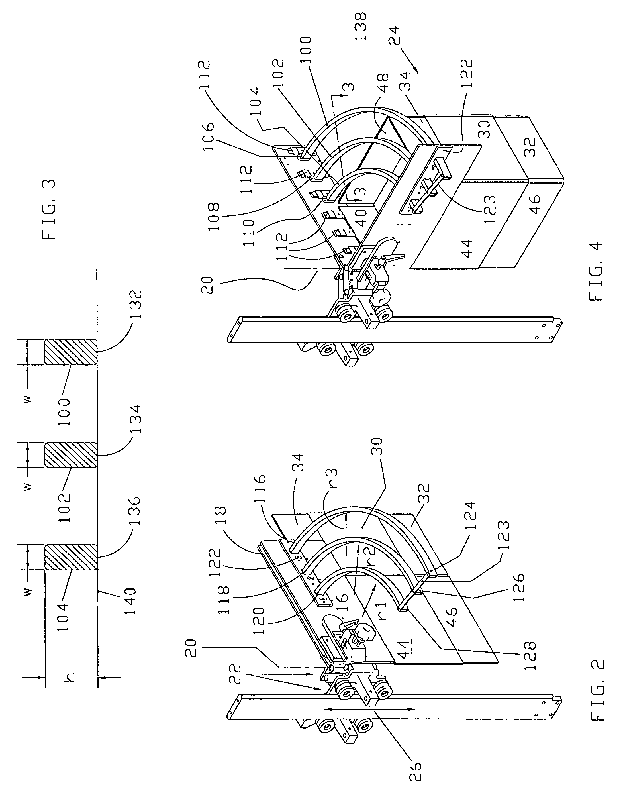
[0025]The erector and sealer 10 is provided with a magazine 12 containing knocked down box blanks which are extracted and squared by the mechanism 14 which include a moveable jaw 16 and a fixed jaw 18. The moveable jaw 16 is pivoted by a suitable drive as represented and indicated by arrow 21 on pivotal axis or hinge 20 between a pick-up or gripping position wherein the jaws 16 and 18 are in opposed substantially parallel position (see FIGS. 2, 5 and 6) and a squaring or open position wherein the jaws are substantially mutually perpendicular as shown in FIGS. 1 and 4. The fixed and moveable jaws 18 and 16 carrying an open or squared case 24 (squared by movement of the jaw 16 to the perpendicular or squaring position) are then moved vertically by the elev...


PUM


Abstract

A case forming machine for erecting cases from knock down case form to an open form and move an opened case downward to a bottom forming station using a fixed and a moveable jaw system is improved by providing a plurality of radially spaced, concentric stabilizer bars fixed to the fixed jaw and arranged to form concentric segments of circles centered on the pivotal axis of the moveable jaw and having their bottom edges in a radial plane relative to the pivotal axis. Also provided is a micrometer type adjustment mechanism that is used for adjusting the gap between the fixed and moveable jaws when the jaws are in the parallel pick-up position.

Description

FIELD OF INVENTION[0001]The present invention relates to a carton or case erector for squaring and erecting a case. More particularly the present invention relates to an improved case stabilizer system capable of stabilizing different sized cases as they are being erected. The present invention also relates to an improved case thickness adjusting system for the erectorBACKGROUND OF THE PRESENT INVENTION[0002]In the manufacture (erection and taping of flaps to produce a carton or case from a knocked down blank) the knocked down carton or case is first squared and then the bottom flaps folded into closed position. The squaring operation generally withdraws a single knocked down case blank from a magazine of such blanks held in face to face position, opens the blank from the knocked down condition into a squared condition wherein adjacent side walls of the case are generally mutually perpendicular and positions the squared blank into a bottom flap folding station. In the bottom flap fo...

Claims


Application Information

Patent Timeline
Patent Type & Authority Patents(United States)
IPC IPC(8): B31B1/78B65B43/30B31B50/78
CPCB31B50/06B31B50/784B31B2100/00B31B2120/30B31B50/78B31B50/80B31B50/804B65B43/265B31B50/0044B65B43/305B31B50/00
Inventor MAKAR, CHRISTOPHER PETERSEWELL, PETER CLIVEPAYNE, BRETT WARREN
Owner WESTERN PACKAGING SYST
Why Eureka
Try Eureka