Hybrid inlet

a hybrid inlet and duct technology, applied in the direction of turbine/propulsion air intakes, air transportation, jet propulsion plants, etc., can solve the problems of weight and size penalties, restricting the location of engine mounting surfaces,

Active Publication Date: 2005-10-20
PRATT & WHITNEY CANADA CORP
View PDF9 Cites 28 Cited by
  • Summary
  • Abstract
  • Description
  • Claims
  • Application Information

AI Technical Summary

Benefits of technology

[0006] The invention provides a turboprop powerplant with at least a compressor having a forward compressor inlet and a shaft extending axially through the compressor and having a shaft axis, an inlet duct encircling the shaft passing therethrough, the inlet duct having an aft ...

Problems solved by technology

A bifurcated duct results in a shorter engine but which restricts the engine mounting surface locations.
As a result, the engine casing structure must...

Method used


Image

  • Hybrid inlet
  • Hybrid inlet
  • Hybrid inlet

Examples


Embodiment Construction

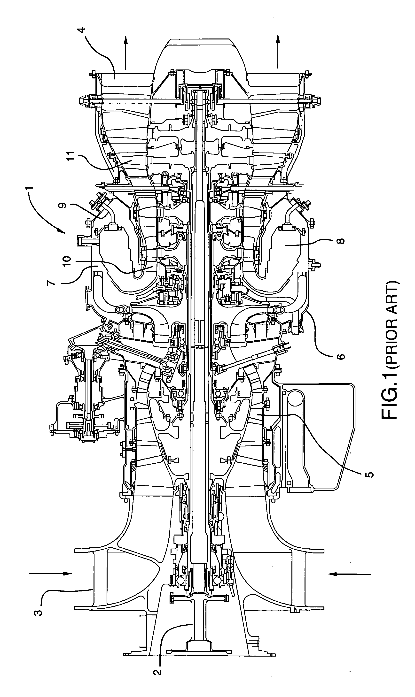
[0019]FIG. 1 shows an axial cross-section through a conventional turboshaft gas turbine engine 1 adapted for rotary wing aircraft to show the main components common to gas turbine engines and display optional configurations for the inlet duct. It will be understood however that the invention is also applicable to any type of gas turbine engine with an inlet duct and a forwardly projecting shaft or gearbox such as a turboprop for fixed wing aircraft, an auxiliary power unit, or stationary electric generator engine. Gas turbine engines are also adapted for non-aircraft applications such as locomotives, ships, military vehicles, fossil fuel pumping and electrical power generation. Depending on the particular arrangement of the engine shaft, engine mounting locations and air inlet duct configuration, the invention may be applied to any such gas turbine engine.

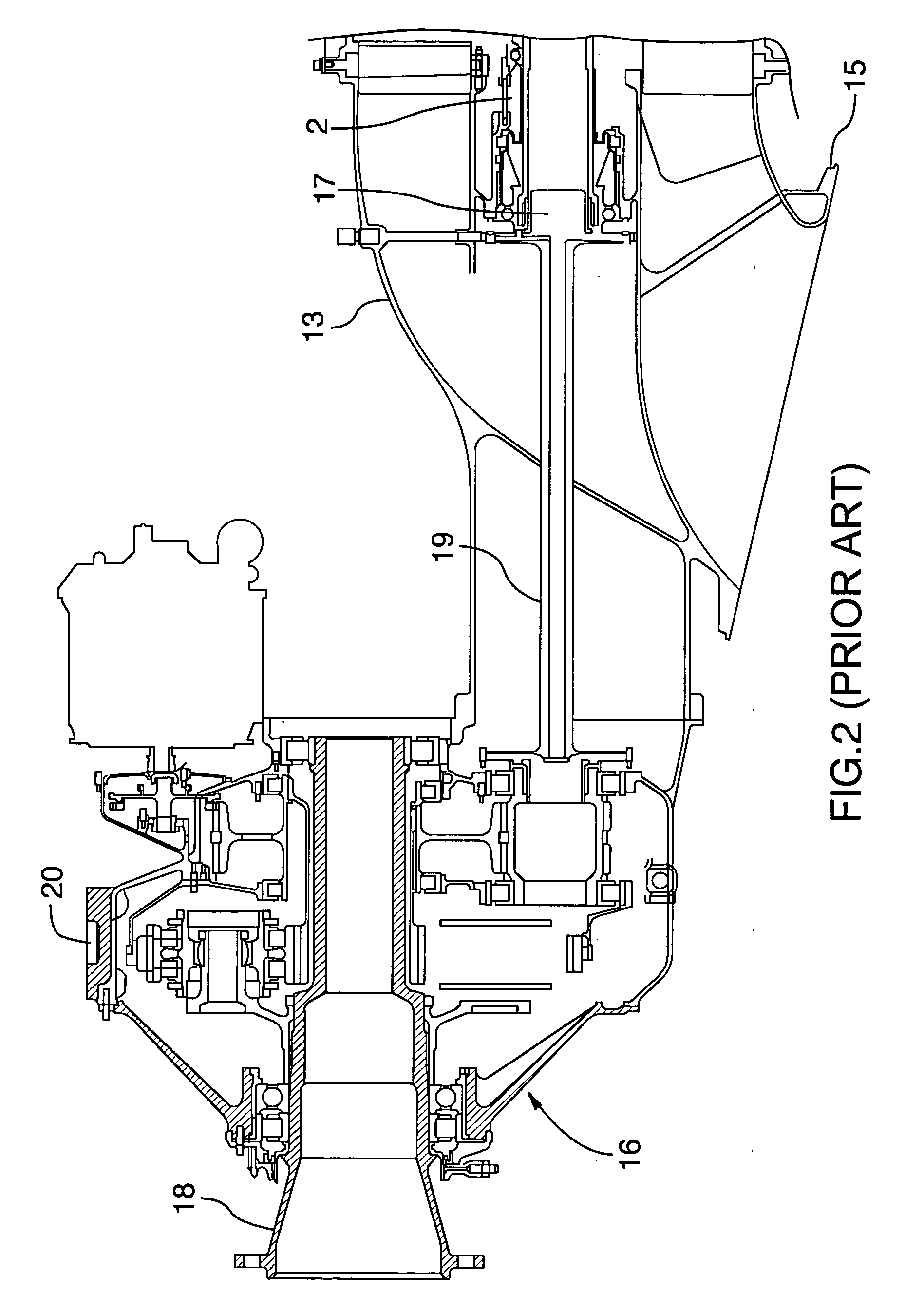
[0020] Air intake into the engine 1 is diverted around the forwardly extending engine shaft 2 through the inlet duct 3 and is ex...


PUM


Abstract

A turboprop powerplant with at least a compressor having a forward compressor inlet and a shaft extending axially through the compressor and having a shaft axis, an inlet duct encircling the shaft passing therethrough, the inlet duct having an aft end in gas communication with the compressor inlet and a forward end having at least two branches each with an inlet orifice, each inlet orifice having a centroid in a radial plane through and transverse to the shaft axis, the centroids and shaft axis defining an angle less than 180°.

Description

TECHNICAL FIELD [0001] The invention relates to a hybrid inlet duct for a gas turbine engine, such as a turboprop, having at least two forwardly open inlet orifices spaced apart less than 180 degrees within a half of the engine, to accommodate a forwardly projecting shaft or gearbox while clearing top and lateral forward engine mounting surfaces. BACKGROUND OF THE ART [0002] Various configurations of gas turbine engines include a forwardly projecting engine shaft about which an air inlet duct is positioned. For example, a turboprop engine and installation may have an upwardly offset reduction gear boxes that drives the propeller and downwardly offset air intake ducts. Further a turboprop may have a coaxial reduction gear box with a bifurcated air inlet duct with an upper and a lower air inlet duct and intake orifice. Especially in the case of aircraft engines, the size and weight of the inlet duct and the effect that the duct geometry has on the size and weight of the engine shaft m...

Claims


Application Information

Patent Timeline
IPC IPC(8): F02C7/04
CPCF02C7/04F05D2250/51F05D2220/324Y02T50/671Y02T50/60Y10T137/0536
Inventor BOUCHARD, GUYSZLANTA, ZENONMITROVIC, LAZAR
Owner PRATT & WHITNEY CANADA CORP
Why Eureka
Try Eureka