Discharge head for the nasal application of liquid from a pressure reservoir

a pressure reservoir and discharge head technology, applied in the direction of inhalators, packaging, transportation and packaging, etc., can solve the problems of rapid contamination of the discharge opening at which liquid may remain after use, unsatisfactory manufacturing accuracy at the discharge opening and at the fluid directing surface upstream of the discharge opening,

Pending Publication Date: 2020-06-04
APTAR RADOLFZELL
View PDF5 Cites 4 Cited by
  • Summary
  • Abstract
  • Description
  • Claims
  • Application Information

AI Technical Summary

Benefits of technology

[0063]It is inherent to a pressure reservoir that the liquid stored therein is always under pressure, and therefore the pressure does not have to be generated for a discharging operation. Various possibilities are provided for exerting the pressure, for example the pressurization by propellent gas or by means of compressed air in the liquid reservoir or in particular in an intermediate region between a bag in the pressure reservoir and the casing wall of the pressure reservoir.

Problems solved by technology

However, disadvantages are also provided.
The discharge opening is therefore at a comparatively far distance from the supply point, which leads to sometimes unsatisfactory manufacturing accuracy at the discharge opening and at fluid directing surfaces upstream of the discharge opening.
This is disadvantageous since the discharge behavior of the liquid may vary by this means from dispenser to dispenser and no longer corresponds to the intended discharge behavior.
In particular, the discharge opening at which liquid may remain after use can become rapidly contaminated.
Rotation from one such end position is associated with an increase in the deformation of one of the components, in particular the outer component, and therefore such a rotation can scarcely take place unintentionally.

Method used


Image

  • Discharge head for the nasal application of liquid from a pressure reservoir
  • Discharge head for the nasal application of liquid from a pressure reservoir
  • Discharge head for the nasal application of liquid from a pressure reservoir

Examples


Embodiment Construction

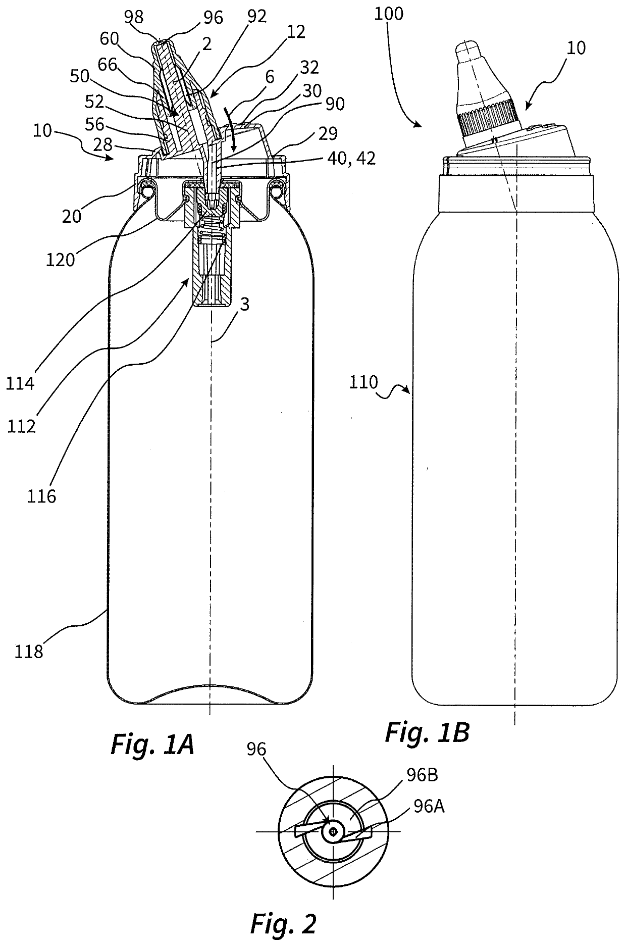
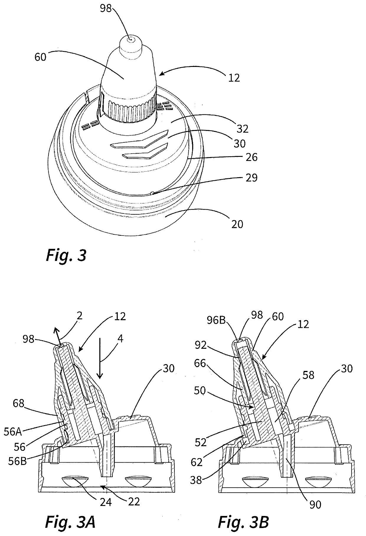
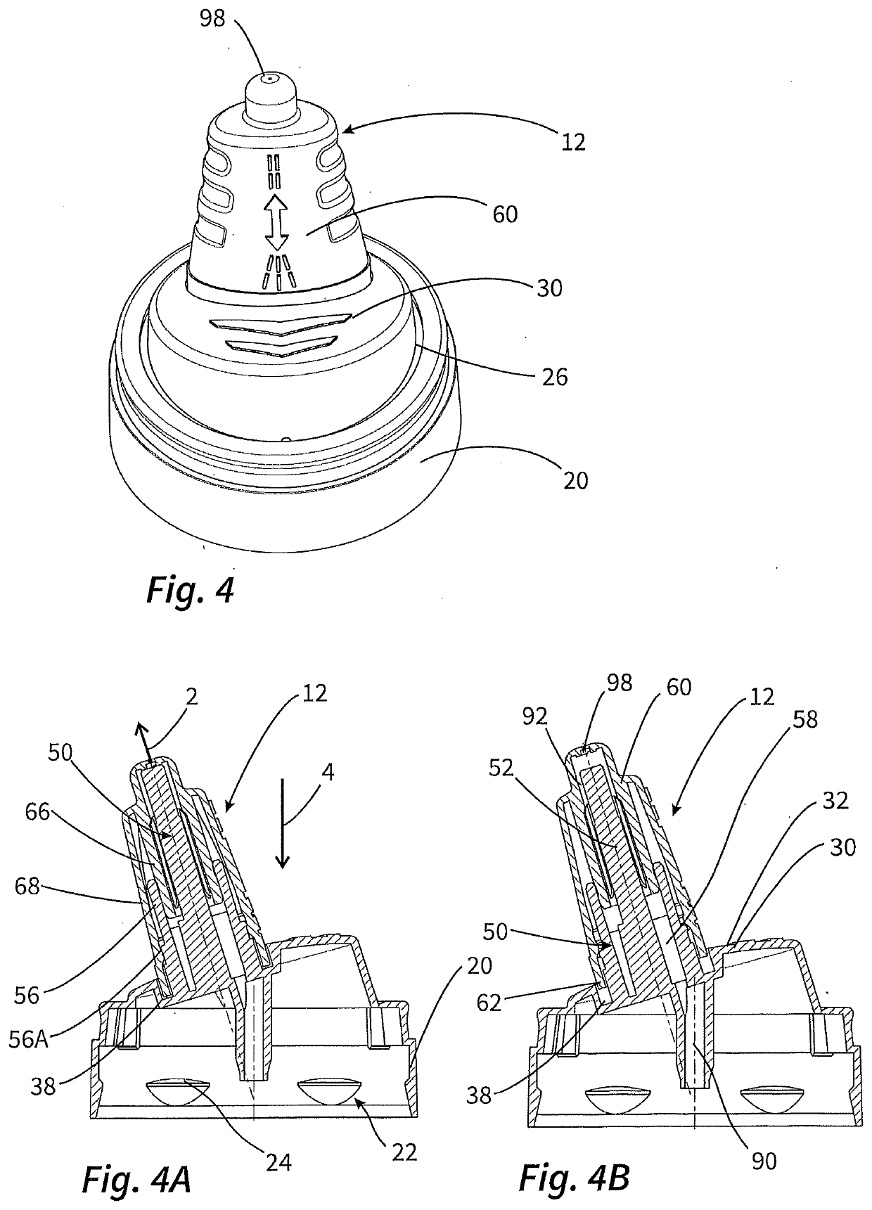
[0070]FIGS. 1A and 1B show an overall illustration of a dispenser 100 according to the invention in a sectioned and unsectioned illustration. The relationships explained below in this regard apply here to various configurations of the discharge head 10 of this dispenser 100. Details regarding two possible configurations of the discharge head 10 will be explained subsequently with reference to FIGS. 3 and 4. A dispenser 100 according to the invention according to the present exemplary embodiments has a pressure reservoir 110, the outer surfaces of which are formed by a metal body 118 and a cover 120. An outlet valve 112 is fastened in the cover 120 and can be opened by pressing down a valve connector 114 counter to the force of a valve spring 116 such that the liquid flows into the discharge head 10.

[0071]The dispenser 100 according to the invention has a slender, elongate nasal applicator 12 on the discharge head 10, the main direction of extent of which nasal applicator is inclined...


PUM


Abstract

A discharge head for the nasal application of pharmaceutical liquid from a pressure reservoir which has an outlet valve with a valve connector, to which force can be applied counter to a spring force in order to open the outlet valve. The discharge head has a nasal applicator which extends outward from an actuating surface and at the end of which a discharge opening is provided. The discharge opening is connected in a fluid-communicating manner to a hollow tube through an applicator channel of the nasal applicator, for connection to the pressure reservoir. The nasal applicator has an inner component connected integrally to the actuating surface and an outer component separate from the inner component and attached to the inner component in a surrounding manner. The discharge opening is provided in the outer component, and the outer component and the inner component together bound the applicator channel.

Description

FIELD OF USE AND PRIOR ART[0001]The invention relates to a discharge head for the nasal application of pharmaceutical liquid from a pressure reservoir which has an outlet valve with a valve connector, to which force can be applied counter to a spring force in order to open the outlet valve. The invention furthermore also relates to a dispenser with such a discharge head.[0002]Similar discharge heads and dispensers are known, for example, from DE 102012200545 A1. The discharge heads disclosed in this document have an outer housing which, firstly, contains the base for the connection to a pressure reservoir and, secondly, forms the outer shell of a nasal applicator together with a discharge opening. An inner component which, together with the outer shell, serves for fluid guidance of liquid to the discharge opening is pushed into the elongate nasal applicator.[0003]A similar design is also known from the US design patent with the publication number US D 659,531 S.[0004]Discharge heads...

Claims


Application Information

Patent Timeline
Patent Type & Authority Applications(United States)
IPC IPC(8): A61M15/08A61M15/00B05B1/12B05B1/34
CPCA61M15/08B05B1/3452A61M15/009B05B1/12B65D83/28B65D83/38B65D83/44A61M11/007B65D83/206B05B1/3436B65D83/226B65D83/228A61M5/145
Inventor GREINER-PERTH, JÜRGENSCHMID, FELIX
Owner APTAR RADOLFZELL
Why Eureka
Try Eureka