Sealing arrangement

Inactive Publication Date: 2006-10-26
BUSAK SHAMBAN GMBH & CO
View PDF10 Cites 11 Cited by
  • Summary
  • Abstract
  • Description
  • Claims
  • Application Information

AI Technical Summary

Benefits of technology

[0009] In the inventive sealing arrangement there is, in all pressure states, a separation between the end of the sealing gap facing the groove and an outer edge of the U-cup facing the sealing gap. Even upon pressurization of up to 400 bars, the U-cup remains completely in the groove (=profiled region of the stationary machine part) and is not extruded into the sealing gap. In cross-section, there always remains a space between the radially oriented region of the profiled section (i.e. the groove wall on the low-pressure side extending perpendicularly to the U-cup axis), the movable machine part and the U-cup. The inventive teaching prevents abrasion between the U-cup and the edges of the sealing gap thereby greatly reducing premature wear of the U-cup.
[0018] Finally, in an advantageous embodiment, the U-cup has an inner surface facing the movable machine part, and the inner surface has microstructures, in particular spherical calottes. This improves the capacity of dragging back hydraulic oil and prevents flat abutment of the U-cup on the movable machine part.

Problems solved by technology

These deformations can damage the U-cup e.g. through abrasion of the U-cup material.
It is not possible to prevent conventional U-cups from being partially pressed into the sealing gap when they are deformed through pressurization, with the result that the U-cups are rapidly worn.

Method used


Image

  • Sealing arrangement
  • Sealing arrangement

Examples


Embodiment Construction

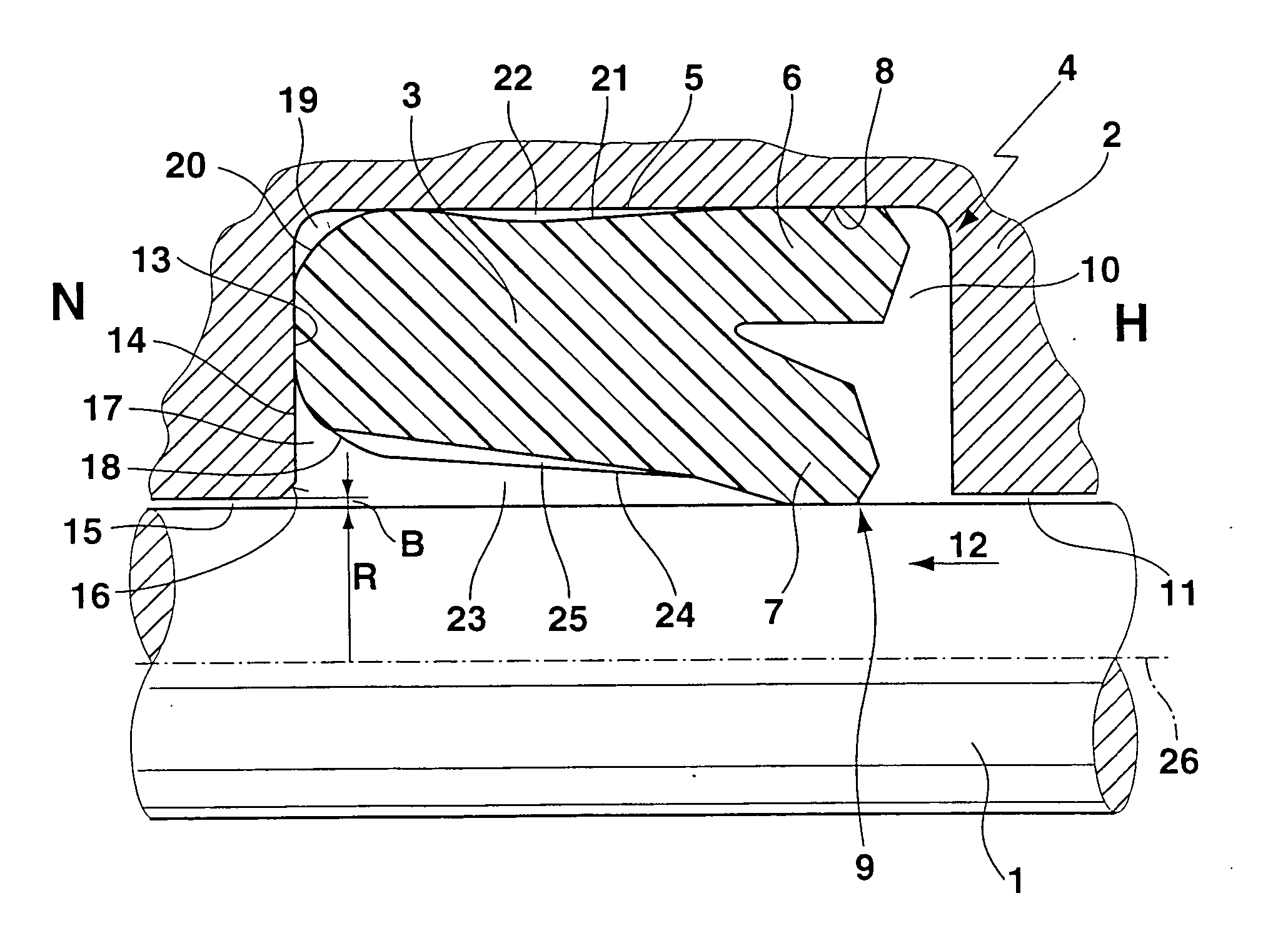
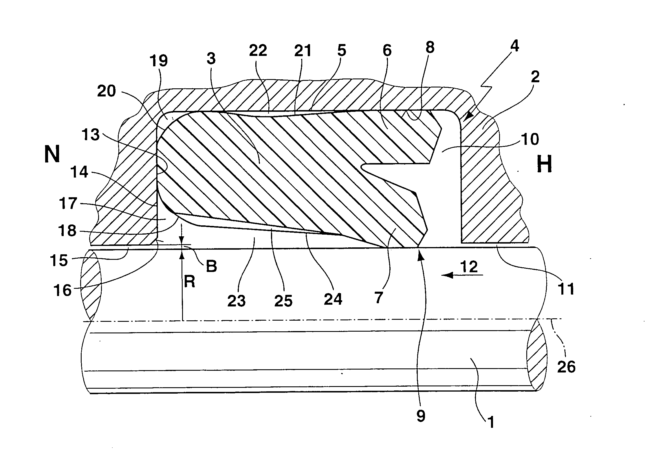
[0022] The FIGURE shows a cross-section of an embodiment of an inventive sealing arrangement in the unpressurized (i.e. largely undeformed) state, comprising a movable machine part 1 which is herein formed as cylindrical piston rod, a stationary machine part 2 and a U-cup 3. The U-cup 3 is associated with an axis 26 with respect to which the U-cup 3 is approximately rotationally symmetrical. The axis 26 coincides with the cylindrical axis of the movable machine part 1. The stationary machine component 2 has a profiled section which is formed as groove 4 having a square cross-section. The U-cup 3 is disposed in the groove 4, wherein, due to radial prestress, i.e. pressure of the U-cup 3 against a groove bottom 5, a sliding motion of the U-cup 3 in the groove 4 is eliminated due to frictional adhesion. The U-cup 3 is formed from a viscoplastic synthetic material, such as polyurethane.

[0023] On the high-pressure side (high-pressure side H, on the right hand side in the FIGURE) the U-c...


PUM


Abstract

In a U-cup based seal of a rod, the basic body of the U-cup 3 is recessed relative to a square cross-sectional shape in the region of a radially inner outer edge 18 on the low pressure side in order to obtain a space 17 between the U-cup 3 and the opening, i.e. the passage opening 16 of a sealing gap 15, leading into a rectangular groove 4 guiding the U-cup 3. This space 17 remains at least partially also upon pressurization such that the U-cup 3 completely remains in the groove 4 upon pressurization and is not extruded into the sealing gap 15. This considerably reduces wear of the U-cup 3.

Description

BACKGROUND OF THE INVENTION [0001] The invention concerns a sealing arrangement for hydraulic pistons or piston rods, comprising a U-cup of a viscoplastic synthetic material, a stationary machine part, and a movable machine part having an outer radius R, wherein the U-cup is disposed as a contacting joint under radial prestress between the stationary machine part and the movable machine part in a profiled section of the stationary machine part, wherein the U-cup has on its high-pressure side a radially outer and a radially inner sealing lip, wherein the stationary and the movable machine parts are separated on the low-pressure side by a sealing gap of a sealing gap width B, wherein, on the low-pressure side, an abutment surface of the U-cup abuts a radially oriented region of the profiled section, and wherein the U-cup has an inner radius and an outer radius. [0002] Sealing arrangements of this type having U-cups are disclosed e.g. by H. K. Müller, “Abdichtung bewegter Maschinenteil...

Claims


Application Information

Patent Timeline
IPC IPC(8): F16J9/20F16J15/16F16J15/32
CPCF16J15/3236F16J15/166
Inventor PETER, JORGPOETHIG, ROLFFRENZEL, ULRICHADOLF, JEAN-JACQUESSCALTRITT, DORIANO
Owner BUSAK SHAMBAN GMBH & CO
Why Eureka
Try Eureka