Self-positioning screw joint

a screw joint and self-positioning technology, which is applied in the direction of threaded fasteners, bolts, transportation and packaging, etc., can solve the problems of large space available for the installation of components, and the lack of necessary space for mounting components on the vehicle, so as to simplify the installation/removal properties and facilitate the installation. , the effect of simple and cost-effective mounting

Active Publication Date: 2020-06-18
SUMITOMO RIKO CO LTD
View PDF0 Cites 0 Cited by
  • Summary
  • Abstract
  • Description
  • Claims
  • Application Information

AI Technical Summary

Benefits of technology

[0004]The embodiments described herein provide a simple and cost-effective mounting system for vehicle components on a vehicle with simplified installation / removal properties.

Problems solved by technology

However, this leads in some cases to the available construction space for the installation of the components either being greatly limited by parts of the vehicle itself or by adjacent components.
The necessary space is therefore often missing for mounting components on the vehicle, for example by tightening a screw and a nut on both sides.

Method used


Image

  • Self-positioning screw joint
  • Self-positioning screw joint
  • Self-positioning screw joint

Examples


Embodiment Construction

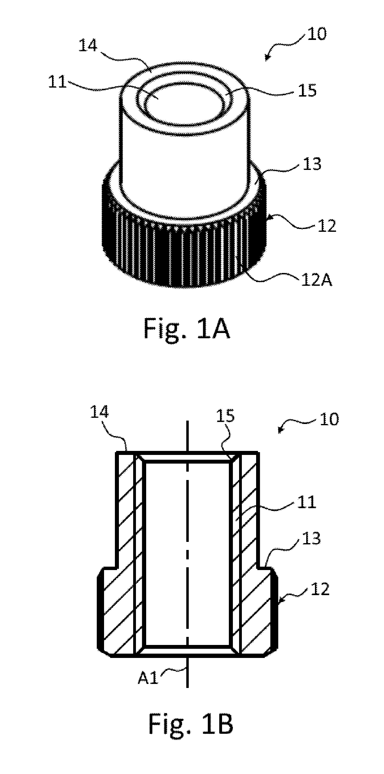
[0041]FIG. 1A shows a perspective view of a bearing bush 10 according to one embodiment. The bearing bush 10 is of substantially cylinder-shape design and includes a bore which runs through the bearing bush 10 and is provided with an internal thread 11. The bore of the bearing bush 10 can alternatively be provided without or at least only partially with an internal thread 11. At least the inner surface of the bore can be formed here from a softer material than the complementary bearing screw 40 (see FIG. 3 et seq.), and therefore, as the bearing screw 40 is screwed into the bore of the bearing bush 10, said bearing screw bites or cuts into the inner surface of the bore of the bearing bush 10.

[0042]The bearing bush 10 furthermore has an encircling fixing portion 12 which protrudes in relation to the rest of the bearing bush 10 radially with respect to an axis A1 of the bearing bush 10. The fixing portion 12 is formed here with a multiplicity of wedges or wedge-shaped projections 12A ...


PUM


Abstract

The disclosure relates to a vehicle component with a bearing bush system for mounting the vehicle component on a fastening portion of a vehicle. The vehicle component includes a bearing bush which has an internal thread, and a bearing bush receptacle which is configured to at least partially accommodate the bearing bush, wherein the bearing bush is configured to be at least partially shifted in the bearing bush receptacle by means of an interaction between the internal thread of the bearing bush and a bearing screw, in order to enter into engagement with the fastening portion. The disclosure furthermore relates to the use of the vehicle component, and to a method for the mounting of the vehicle component.

Description

CROSS REFERENCE TO RELATED APPLICATIONS[0001]This application claims the benefit of DE Patent Application No. 10 2017 007 051.2 filed Jul. 26, 2017, which is hereby incorporated by reference in its entirety.BACKGROUND[0002]The disclosure relates to a vehicle component with a bearing bush system for mounting the vehicle component on a fastening portion of a vehicle, to the use of such a vehicle component for mounting the vehicle component, and to a method for the mounting of the vehicle component on the fastening portion of the vehicle.[0003]The field of the disclosure resides in the field of mountings for vehicle components, in particular in the field of bearing bush systems. In modern vehicles, a multiplicity of very different components are mounted and fastened. However, this leads in some cases to the available construction space for the installation of the components either being greatly limited by parts of the vehicle itself or by adjacent components. The necessary space is the...

Claims


Application Information

Patent Timeline
Patent Type & Authority Applications(United States)
IPC IPC(8): F16C33/08F16C17/02
CPCF16C33/08F16C17/02B62D27/065F16B37/145F16B33/002F16B41/002F16B5/0642F16B9/054F16B37/00F16B37/068
Inventor IRAKI, YOUSSEFGROMES, MARTIN
Owner SUMITOMO RIKO CO LTD
Why Eureka
Try Eureka