Electric parking brake

a technology of parking brake and electric motor, which is applied in the direction of braking system, friction lining, transportation and packaging, etc., can solve the problems of design disadvantage and adverse effects, and achieve the effects of simple design, simple mounting, and simple structur

Inactive Publication Date: 2014-02-25
ROBERT BOSCH GMBH
View PDF12 Cites 0 Cited by
  • Summary
  • Abstract
  • Description
  • Claims
  • Application Information

AI Technical Summary

Benefits of technology

[0003]The electric parking brake of the invention has, in contrast, the advantage that while having a simple design and involving simple, cost-effective mounting it brings about radial centering between a brake caliper and a motor / gear unit only by means of torque-transmitting parts. Therefore, overdeterminedness of the centering, as in the prior art, cannot occur. This is achieved according to the invention in that a spindle is connected axially directly to an output shaft of the motor / gear unit. In this context, the spindle is centered on the output shaft and is mounted in a brake caliper. An interface can therefore be implemented between the brake caliper and the motor / gear unit by means of a direct connection of the spindle to the output shaft and bearing of the spindle in the brake caliper. This makes it possible to avoid stressing of the components during the mounting of the transmission on the brake caliper due to unfavorable tolerance additions.
[0007]According to a further preferred configuration of the present invention, a sealing element is provided, which seals off a gap running in the radial direction, the sealing element having a sealing face directed in the axial direction. This makes it possible to make available a defined sealing face in the axial direction, which forms a seal between the brake caliper and the motor / gear unit. This ensures a seal which is improved compared to the prior art since the arrangement of the seal at the gap running in the radial direction avoids non-uniform application of force owing to incorrect centering.
[0008]Furthermore, the electric parking brake according to the invention preferably has a corrosion-relief groove, which avoids the occurrence of gap corrosion at the radial sealing gap. The corrosion-relief groove is arranged radially outside the sealing element here. The geometric formation of the corrosion-relief groove makes it possible to avoid corrosion occurring directly at the sealing element since when corrosion occurs it occurs at the corrosion-relief groove. The corrosion-relief groove therefore protects against corrosion occurring in the sealing element region and therefore giving rise to a leak.

Problems solved by technology

In this context, it has been found that this design has the disadvantage of stress, in particular during mounting, since overdeterminedness occurs as a result of coaxiality errors between the centering collar and a spindle and centering on the centering internal diameter of the motor / gear unit and the output shaft.
As a result, during mounting stresses occur which give rise to adverse effects during the transmission of torque since said stresses significantly reduce the efficiency and also durability, and also have sealing problems between the brake caliper and the motor / gear unit.

Method used


Image

  • Electric parking brake
  • Electric parking brake

Examples


Embodiment Construction

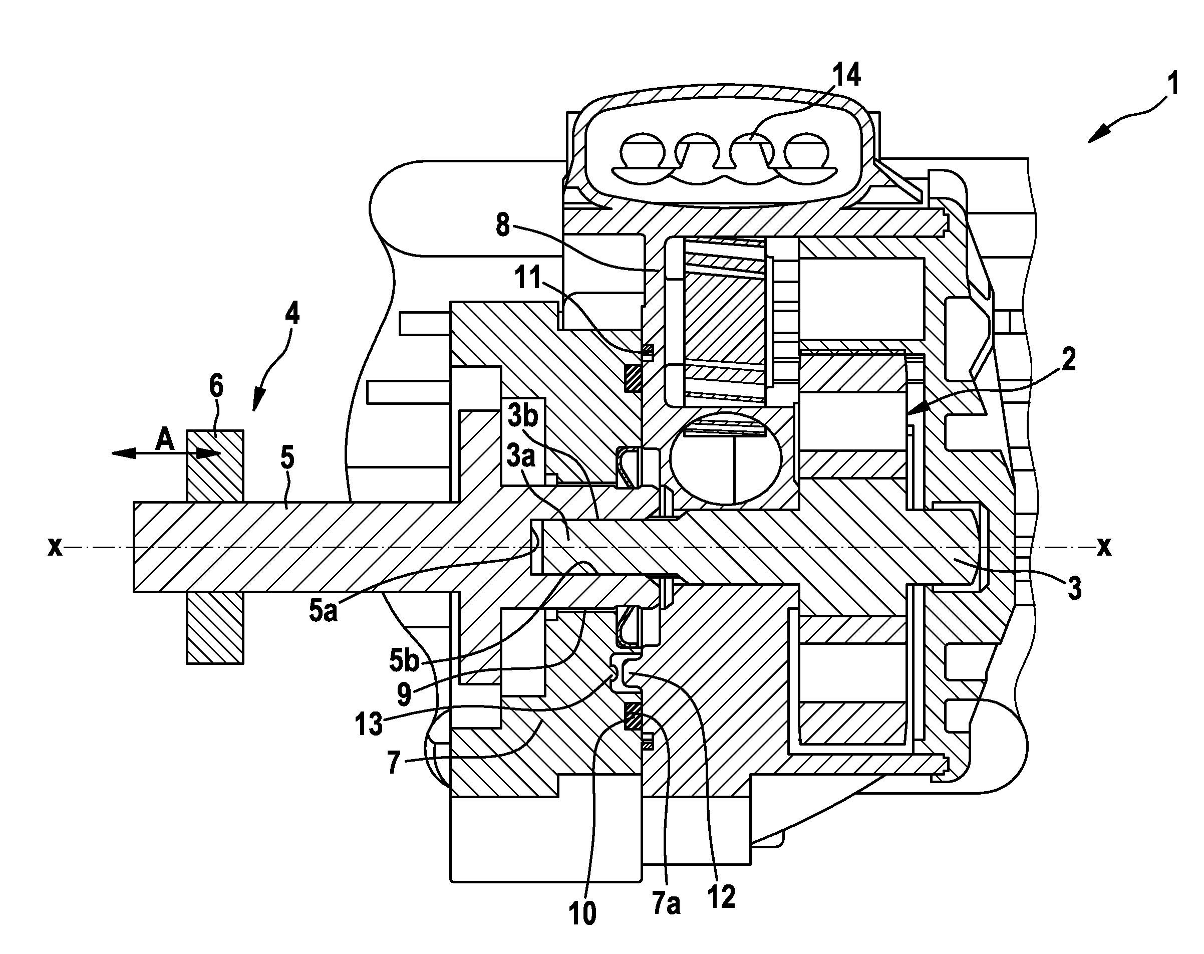
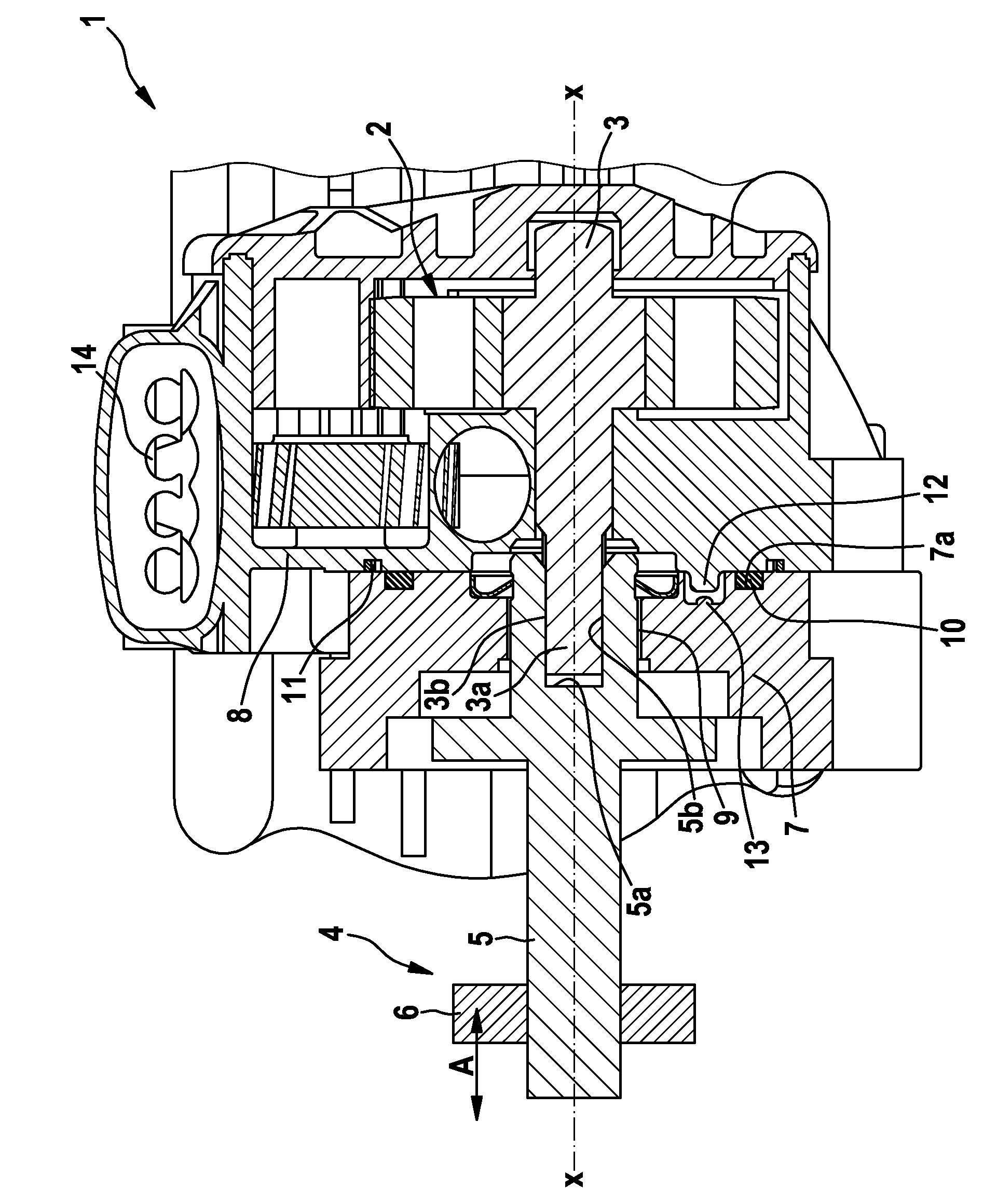
[0014]An electric parking brake 1 according to an exemplary embodiment of the invention will be described below with reference to FIG. 1.

[0015]As is apparent from FIG. 1, the electric parking brake 1 comprises a motor / gear unit 2, which is illustrated only schematically in FIG. 1. The motor / gear unit 2 comprises a compact electric motor and a gear unit, which comprises a plurality of gear wheel elements. The motor / gear unit 2 also comprises an output shaft 3 at which an output torque is output. As is apparent from FIG. 1, the output shaft 3 is arranged in an axial direction X-X of the electric parking brake 1. A region 3a with a relatively small diameter is formed at the free end of the output shaft 3. A toothing arrangement 3b, which is in engagement with a toothing arrangement 5b of a spindle 5, is provided at this region 3a. The toothing arrangement 5b is of complementary design to the toothing arrangement 3b here in an axial central recess 5a of the spindle 5. The spindle 5 is p...


PUM


Abstract

The invention relates to an electric parking brake, comprising a motor-gearing unit (2) with a drive output shaft (3), wherein the motor-gearing unit (2) generates a rotation of the drive output shaft (3), and comprising a spindle device (4) having a spindle (5) and a nut (6), wherein the spindle device (4) converts the rotation of the drive output shaft (3) into an axial movement of the nut (6) in the axial direction (X-X), wherein the spindle (5) is connected in a positively locking manner to the drive output shaft (3), the spindle (5) is centered on the drive output shaft (3), and the spindle is mounted in a brake caliper (7).

Description

BACKGROUND OF THE INVENTION[0001]The present invention relates to an electric parking brake having an improved interface between a brake caliper and a drive for activating the parking brake.[0002]In recent times, electric parking brakes, which are intended to replace the customary Bowden cable handbrakes, are being increasingly installed in vehicles. What are referred to as motor / gear units, which have an electric motor and a transmission for changing the rotational speed in a compact design, are frequently used as a drive for activating the electric handbrake by means of an actuator, for example a spindle device. Such motor / gear units have previously been centered radially by means of an outer collar on the brake caliper and a centering internal diameter on a housing of the motor / gear unit. In this context, it has been found that this design has the disadvantage of stress, in particular during mounting, since overdeterminedness occurs as a result of coaxiality errors between the ce...

Claims


Application Information

Patent Timeline
Patent Type & Authority Patents(United States)
IPC IPC(8): F16D65/18F16D55/00
CPCF16D2125/40F16D2121/24B60T11/04F16D65/18B60T13/746
Inventor SCHEMEL, HANS-PETERMEIER, HELMUTOCHS, HARTMUT
Owner ROBERT BOSCH GMBH
Why Eureka
Try Eureka