Pipetting system
a pipetting system and pipette tip technology, applied in the direction of pipettes/pipettes, supporting devices, instruments, etc., can solve the problems of inability to receive conventional grippers or other tools with pipette tip receptacles, high cost of disposable tips in continuous operation, and additional disposal costs
- Summary
- Abstract
- Description
- Claims
- Application Information
AI Technical Summary
Benefits of technology
Problems solved by technology
Method used
Image

Examples
Embodiment Construction
[0003]An object of the present invention consists in providing a pipetting system in which a gripper can be used together with an inserted pipette tip.
[0004]This object is solved by a pipetting system having the features of claim 1. Further embodiments of the pipetting system are defined by the features of further claims.
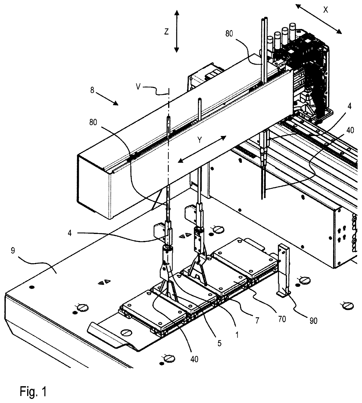
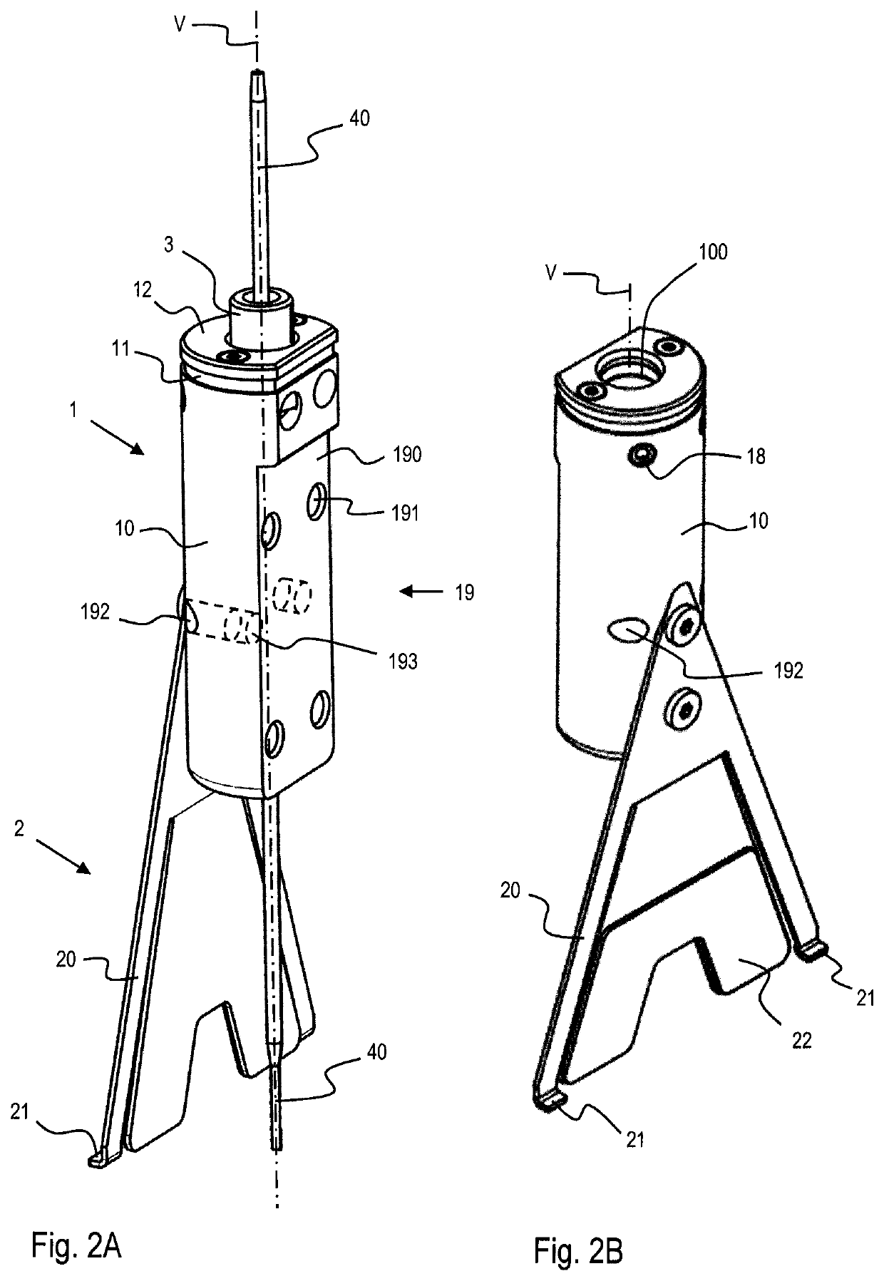
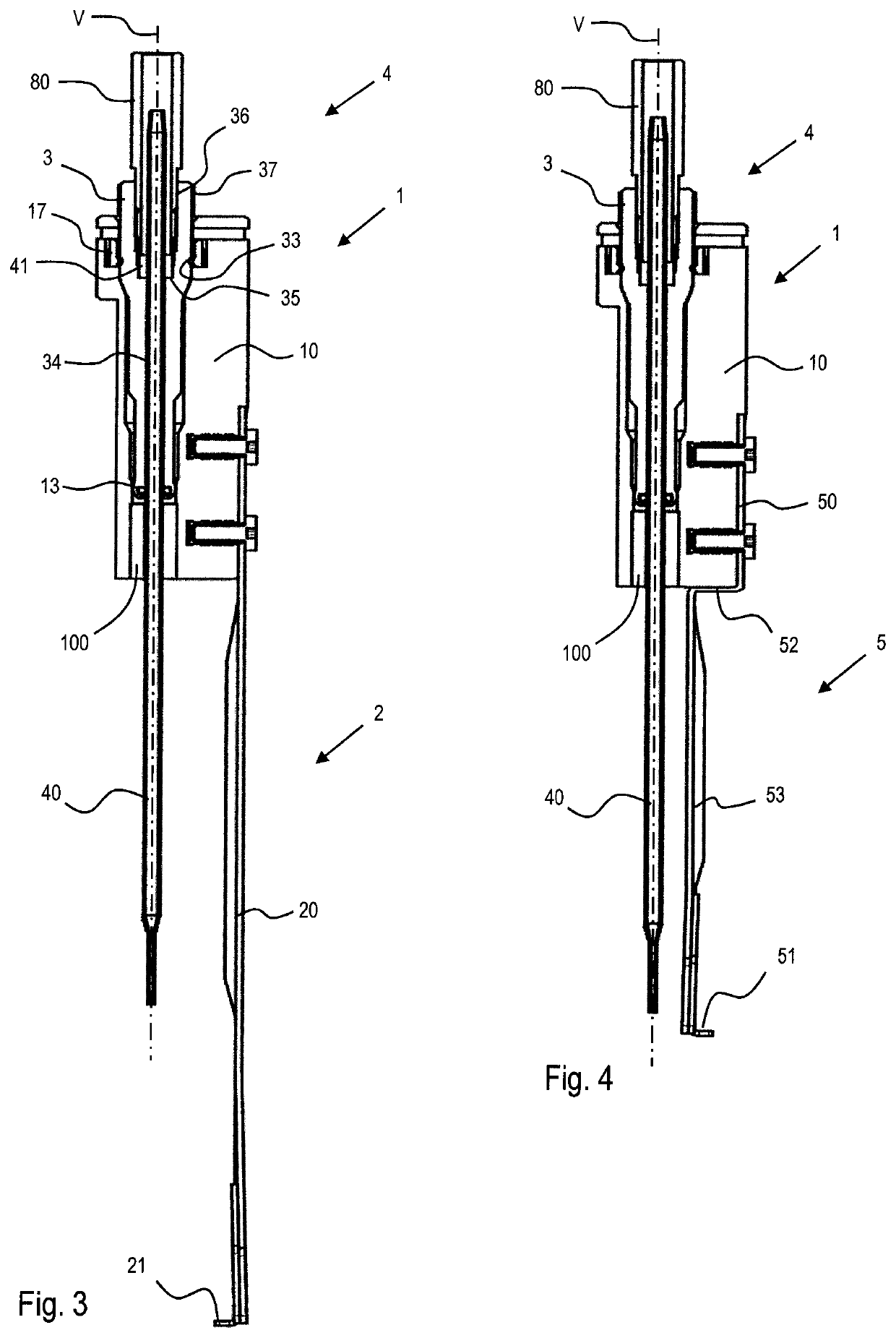
[0005]A pipetting system according to the invention comprises at least one pipette tip receptacle with a pipette tip arranged therein, which extends along a vertical axis, at least one gripper comprising a mechanical coupling which extends along the vertical axis, wherein the gripper with the coupling is coupled to at least one pipette tip receptacle and at least one grip element which extends from the coupling along the vertical axis, wherein the at least one grip element comprises at least one substantially vertical portion, wherein the coupling comprises a body having a through channel which extends along the vertical axis over the entire length of the coupling a...
PUM
| Property | Measurement | Unit |
|---|---|---|
| distance | aaaaa | aaaaa |
| distance | aaaaa | aaaaa |
| distance | aaaaa | aaaaa |
Abstract
Description
Claims
Application Information
 - R&D
- Intellectual Property
- Life Sciences
- Materials
- Tech Scout
- Unparalleled Data Quality
- Higher Quality Content
- 60% Fewer Hallucinations
Browse by: Latest US Patents, China's latest patents, Technical Efficacy Thesaurus, Application Domain, Technology Topic, Popular Technical Reports.
© 2025 PatSnap. All rights reserved.Legal|Privacy policy|Modern Slavery Act Transparency Statement|Sitemap|About US| Contact US: help@patsnap.com