
Method for transmitting data in camera module

a technology of camera module and data transmission, applied in the field of camera module, can solve the problems of shake correction performance and auto-focusing performance, disturbance of images, and inability to perform normal auto-focusing, and achieve the effect of longer transmission time, faster transmission rate and increased communication ra

Active Publication Date: 2020-06-18
DONG WOON ANATECH CO LTD
View PDF0 Cites 4 Cited by
  • Summary
  • Abstract
  • Description
  • Claims
  • Application Information

AI Technical Summary

Benefits of technology

The present invention describes a data transmission method that allows for the efficient transmission of information without the need for faster transmission rates or longer transmission times. This method uses a two-wire interface method that minimizes physical connections between data transmission entities, and it allows for the transmission and reception of newly added information without increasing the communication rate. The technical effect of this method is reduced data transmission time and cost.

Problems solved by technology

In portable devices equipped with camera modules, as mobility and portability increase, there occurs a phenomenon in which images are disturbed due to minute vibrations or shaking generated by a human body.
Meanwhile, shake correction performance and auto-focusing performance are affected by a temperature inside the camera module.
In addition, in the case of the optical axis of the actuator, a lens is affected due to the temperature variation such that a problem occurs in that auto focusing is not performed normally.
In this case, when information (e.g., temperature information in the camera module) which should be additionally transmitted is increased, the additional information may not be completely transmitted due to a data rate limitation of the two-wire interface method.

Method used


Image

  • Method for transmitting data in camera module
  • Method for transmitting data in camera module
  • Method for transmitting data in camera module

Examples


Embodiment Construction

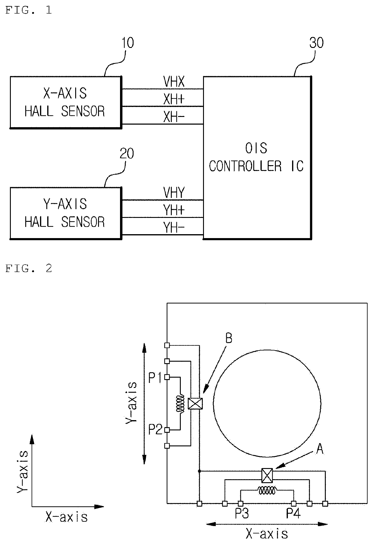
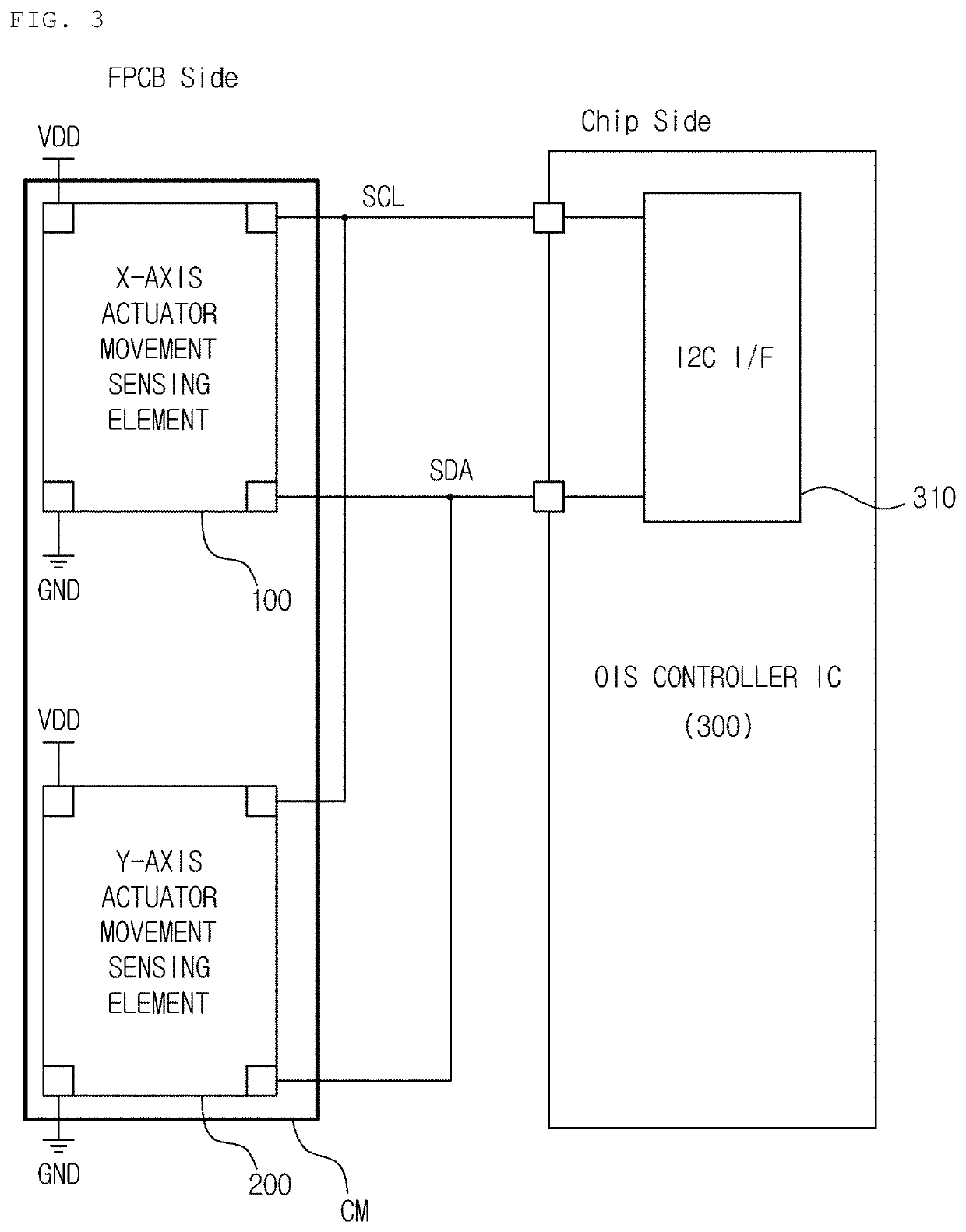
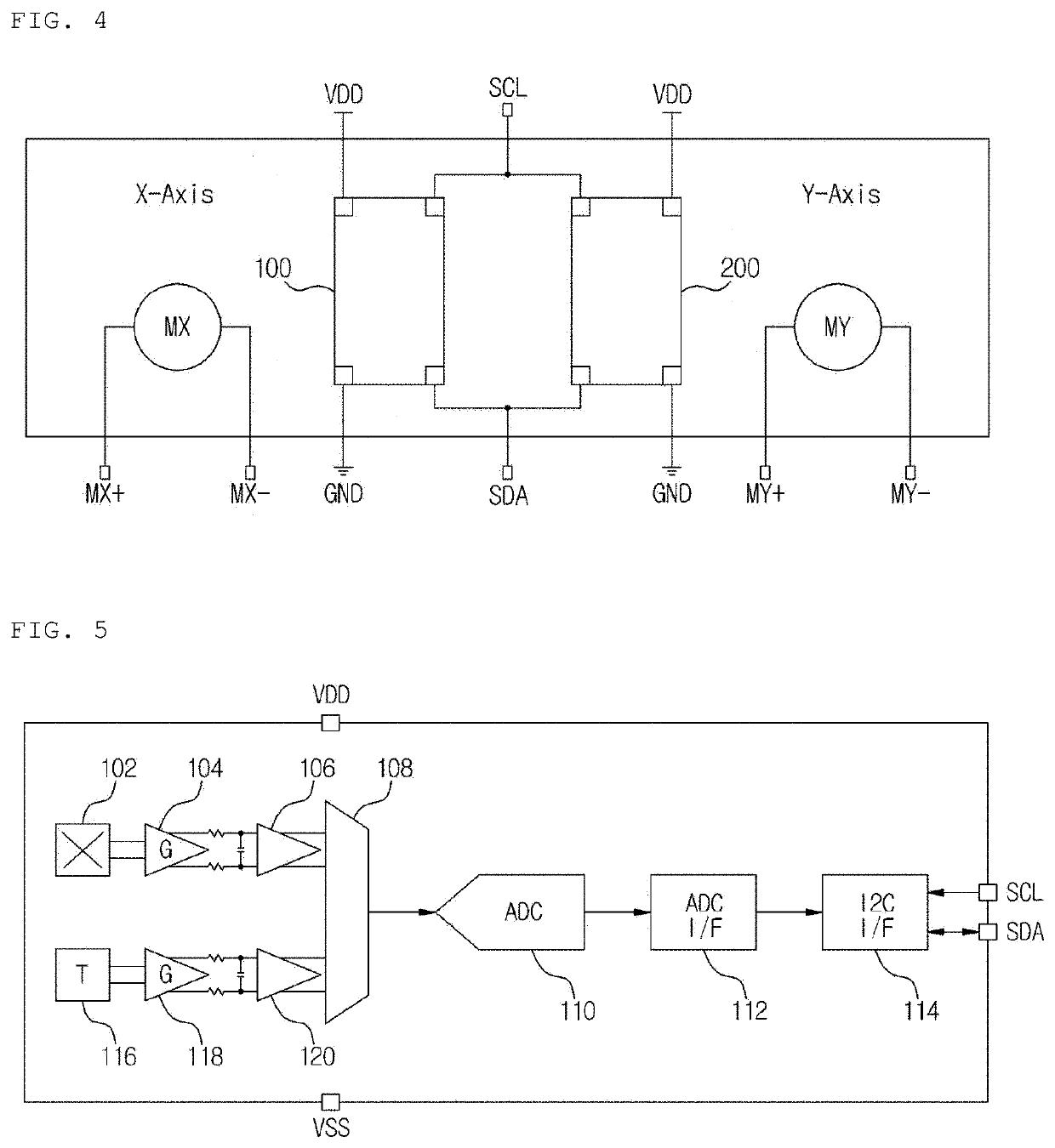
[0030]Hereinafter, exemplary embodiments of the present invention will be described in detail with reference to the accompanying drawings. In the following description of the present invention, when related known functions or configurations are determined to obscure the gist of the present invention, a detailed description thereof will be omitted herein. For reference, among terms used in the following description and the accompanying drawings, position XH (YH or ZH) is axial movement distance sensing data of a first transmission section transmitted from actuator movement sensing elements to an optical image stabilization (OIS) controller integrated circuit (IC), and position X (Y or Z) is each piece of axial movement distance sensing data transmitted in a transmission section next to the first transmission section. Position XH (YH or ZH) and position X (Y or Z) are defined as representing increments between previously transmitted axial movement distance sensing data and currently s...


PUM


Abstract

The present invention relates to a method for transmitting data in a camera module which transmits data necessary for camera shake correction, and the present invention comprises a first step in which each actuator movement detection element sequentially transmits the axial movement distance detection data detected through a Hall sensor in a two-wire interface manner without correction after each specified time delay, in a first transmission section in which each piece of axial movement distance detection data of the actuator has to be transmitted to a controller module for a shake correction; and a second step in which each actuator movement detection element sets just the variation between previously transmitted axial movement distance data and currently detected axial movement distance detection data as each piece of axial movement distance detection data with respect to each axis and sequentially transmits in the two-wire manner after the same specified time delay, respectively, in a transmission section after the first transmission period.

Description

TECHNICAL FIELD[0001]This invention relates to a camera module, and more particularly, to a method of transmitting data in a camera module which transmits data necessary for camera shake correction.BACKGROUND ART[0002]In portable devices equipped with camera modules, as mobility and portability increase, there occurs a phenomenon in which images are disturbed due to minute vibrations or shaking generated by a human body. As measures for obtaining clear images, camera modules equipped with shake correction devices (or technologies) have become common. The shake correction devices (technologies) are classified into digital image stabilization (DIS) methods, electronic image stabilization (EIS) methods, and optical image stabilization (OIS) methods. In terms of performance, the OIS methods are widely used.[0003]In a shake correction device using an OIS method, a Hall sensor is basically used to receive feedback of a movement distance of an actuator (or a carrier in a narrow sense). Tha...

Claims


Application Information

Patent Timeline
Patent Type & Authority Applications(United States)
IPC IPC(8): H04N5/232G03B5/04
CPCG03B2205/0015G03B5/04H04N5/23287G02B27/646G03B2206/00G03B2217/005G03B2205/0007G03B5/02H04N23/687
Inventor BYUN, JAE HYEOKJIN, JUNG HOPARK, JIN
Owner DONG WOON ANATECH CO LTD
Learn More