
Atomizing device

Active Publication Date: 2020-07-02
SHENZHEN SMOORE TECH LTD
View PDF0 Cites 2 Cited by
  • Summary
  • Abstract
  • Description
  • Claims
  • Application Information

AI Technical Summary

Benefits of technology

The invention is an atomizing device that has a bending section, which makes it difficult for liquid to reach the puff sensor. This improves the safety and lifespan of the device.

Problems solved by technology

The liquid in the atomizer likely flow to the puff sensor when leaking out through the air inlet, causing the puff sensor to fail, and the main body is scrapped.

Method used


Image

  • Atomizing device
  • Atomizing device
  • Atomizing device

Examples


Embodiment Construction

[0026]In order to render a more apparent understanding of technical features, objects, and effects of the present invention, specific embodiments thereof will be described in detail with reference to the accompanying drawings.

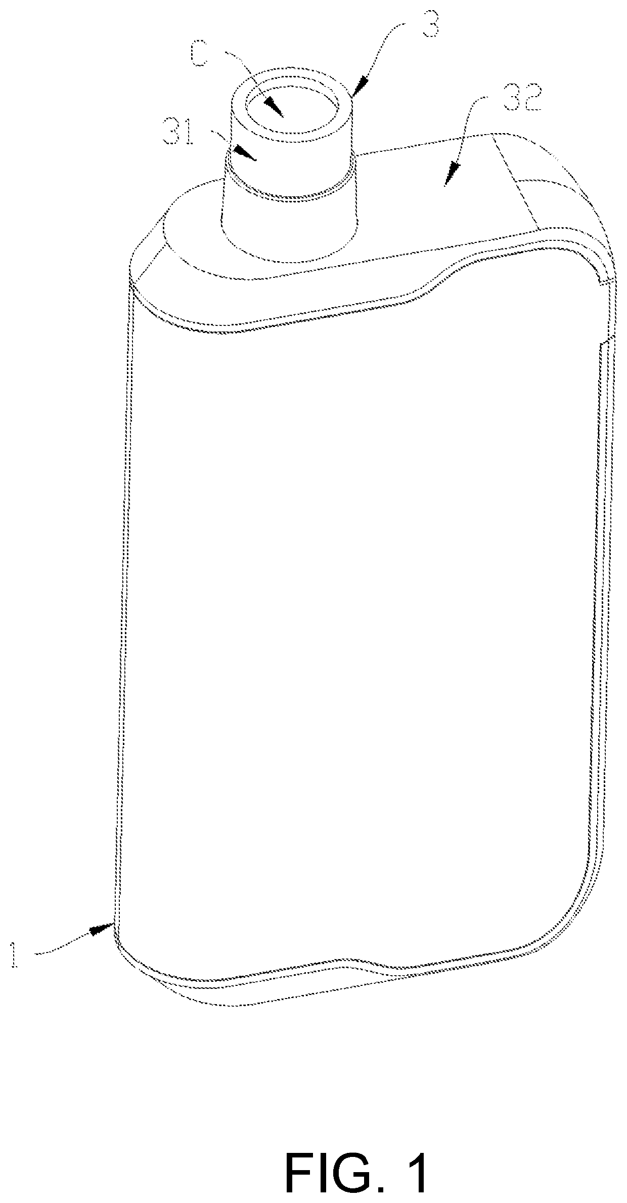
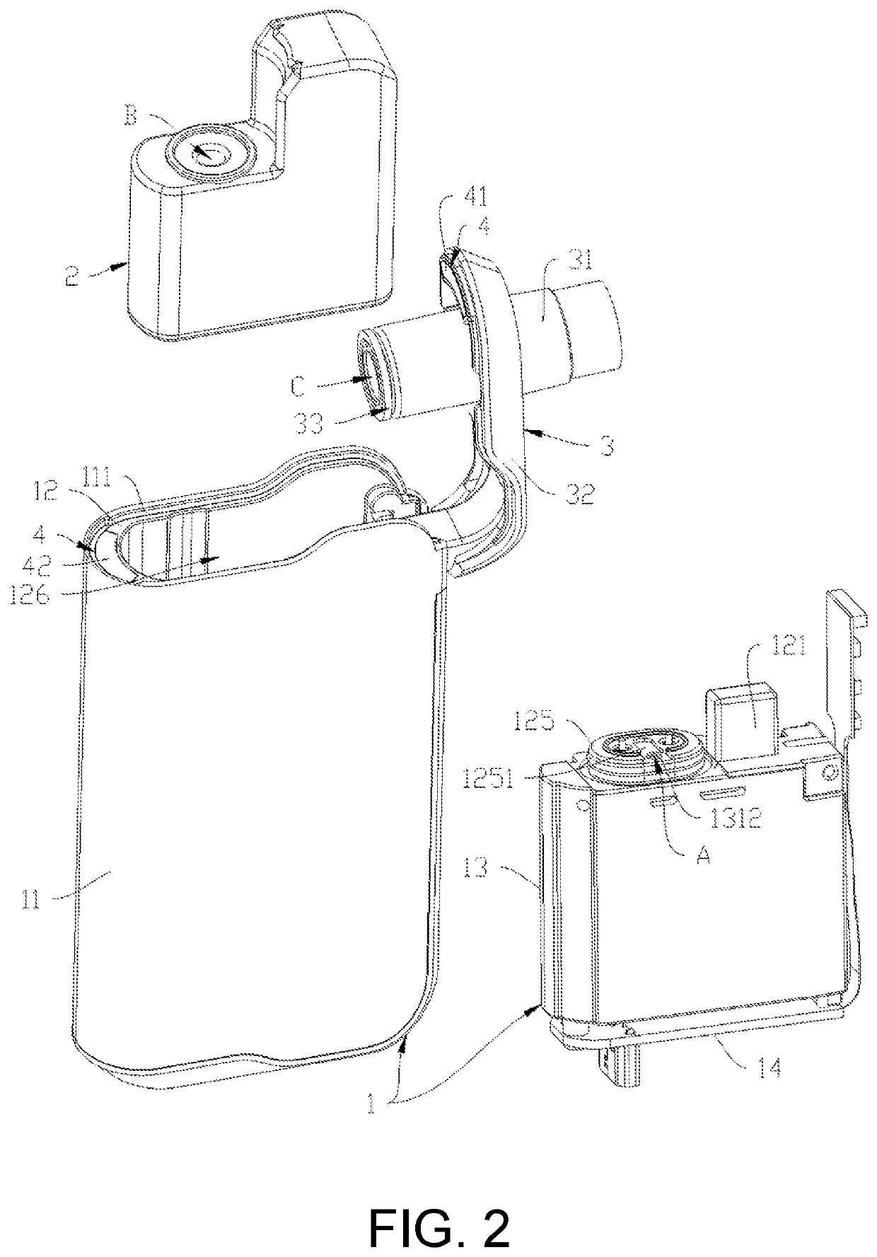
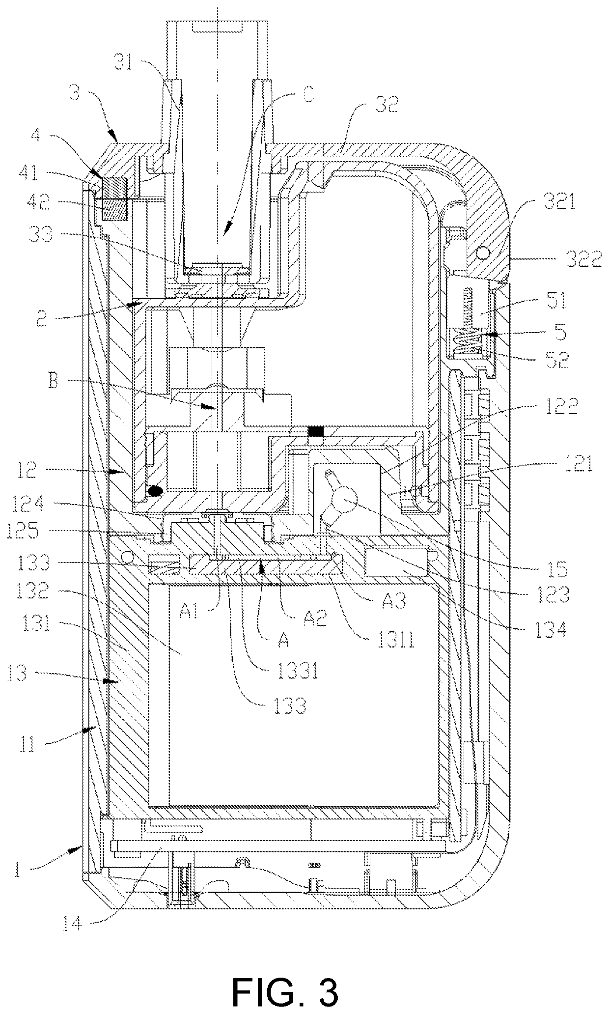
[0027]As shown in FIG. 1 to FIG. 4, an atomizing device in an embodiment of the present invention includes a main body 1, an atomizer 2, and a suction nozzle assembly 3.

[0028]The main body 1 includes an outer housing 11, an inner housing 12, a battery assembly 13, and a control circuit board 14. The inner housing 12, the battery assembly 13, and the control circuit board 14 are disposed in the outer housing 11. An opening 111 is defined at one end of the outer housing 11. The battery assembly 13 is provided at a bottom of the outer housing 11 opposite to the opening 111.

[0029]The inner housing 12 is positioned in the outer housing 11 and abuts against the battery assembly 13, to retain the battery assembly 13 to the bottom of the outer housing 11. A receiving c...


PUM


Abstract

An atomizing device includes an atomizer, a puff sensor and an airflow passage. A transfer passage is defined in the atomizer, and two end portions of the airflow passage are respectively fluidly communicated with the transfer passage and the puff sensor. The airflow passage comprises a bending section, which is configured to prevent liquid in the atomizer from flowing to the puff sensor. With the bending section, liquid is difficult to reach the puff sensor even if it flows into the main body, therefore the safety and the service life of the atomizing device are improved.

Description

CROSS-REFERENCE TO RELATED APPLICATION[0001]This present invention claims the priority benefit of China application serial no. 201811604093.3, filed on Dec. 26, 2018. The entirety of the above-mentioned patent application is hereby incorporated by reference herein and made a part of this specification.BACKGROUNDTechnical Field[0002]The present invention relates to the technical field of atomization, and specifically to an atomizing device.Description of Related Art[0003]An atomizing device mainly includes an atomizer for atomizing liquid and a main body for supplying power to the atomizer. There are two conventional ways to start the atomizing devices. Wherein, one way is to start by pressing a button, and another way is to start by a user's drawing operation sensed by a puff sensor.[0004]The puff sensor in the conventional atomizing device is generally disposed in the main body. The atomizer generally includes a suction nozzle end away from the main body and an air inlet end proxim...

Claims


Application Information

Patent Timeline
IPC IPC(8): A24F40/51A24F40/10A24F40/40
CPCA24F40/51A24F40/40A24F40/10A24F40/485
Inventor WEN, ZHIHUA
Owner SHENZHEN SMOORE TECH LTD
Learn More