System and method for bodily support

a system and support technology, applied in the field of support equipment, can solve the problems of inability to facilitate ambulatory functions, inhibit the user/patient's ability to use the system effectively, and are typically not wheelchair accessible, and achieve the effect of convenient transportation

Active Publication Date: 2020-07-02
LEFKOTEK LLC
View PDF0 Cites 3 Cited by
  • Summary
  • Abstract
  • Description
  • Claims
  • Application Information

AI Technical Summary

Benefits of technology

[0015]According to certain embodiments of the present invention, the system can include a front support component configured with handles and a chest protection pad to prevent the user's torso from moving too far forward and into the mechanical components of the system when the user is positioned on the seat of the system.
[0017]According to an exemplary embodiment of the present invention, the lifting mechanism can be configured as an actuator that can restrict extension of the extension arm connected to the second end of the lever arm, which can then prevent the upward movement of the second end of the lever arm, and thus the downward movement of the seat end of the lever arm. A user can use the system by using the control device to select a desired amount of body weight support. The control device, in conjunction with the lifting mechanism operating system, can then adjust the body weight support force provided by the lifting mechanism to an amount that prevents downward movement of the seat end of the lever arm unless the user applies more body weight than the selected body weight support amount force. The user can then position himself or herself onto the seat end of the lever arm and begin exercising.

Problems solved by technology

However, these commonly known supportive exercise systems have several limitations that inhibit the user's / patient's ability to use the systems effectively.
For example, such systems are typically not wheelchair accessible, do not allow for ambulatory functions, require assistance from another person, such as a trainer, to enter and use the system, place stress on the user's body due to the harness, and are not efficient at allowing the user to effectively regain strength due to the lifting forces of the weight bearing relief components of the system.

Method used


Image

  • System and method for bodily support
  • System and method for bodily support
  • System and method for bodily support

Examples


exemplary embodiment # 1

Exemplary Embodiment #1

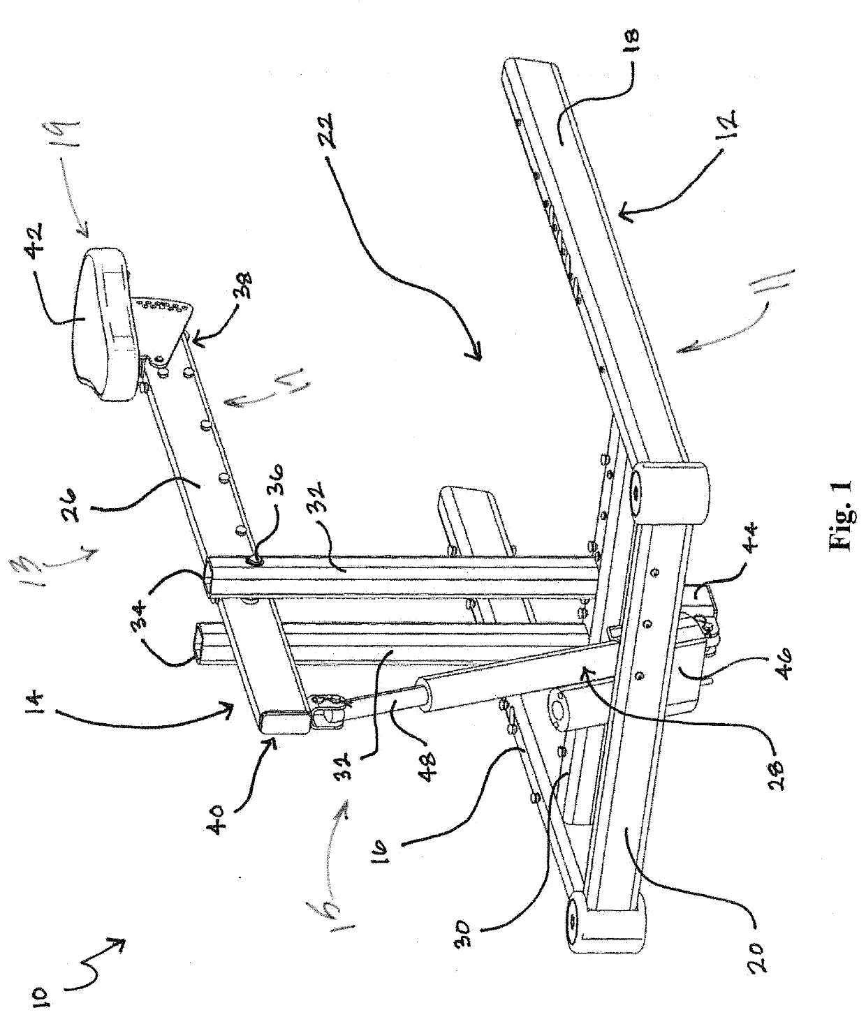
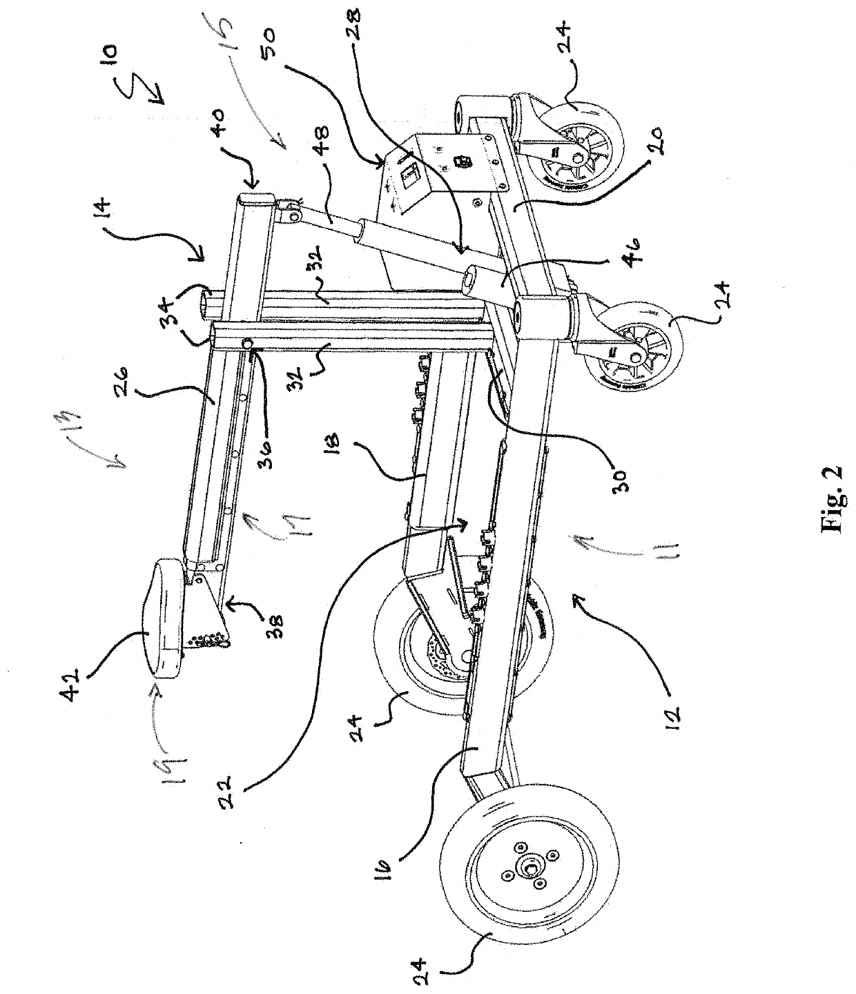
[0074]System 10 according to one exemplary embodiment hereof will be described in greater detail. According to such an embodiment, system 10 can include a frame portion 12 and a weight supporting portion 14 as described above. As best shown in FIG. 1, weight supporting portion 14 can be mounted onto frame portion 12 by a support structure (described below) and can include a rotating lever arm 26 actuated by lifting mechanism 28 configured an actuator 28 in order to provide the weight support functionality of system 10. The support structure for mounting lever arm 26 to frame portion 12 can include a crossbar member 30 extending across frame portion 12 and one or more support columns 32 extending upward from crossbar member 30. As best shown in FIGS. 1 and 2, crossbar member 30 can be located within the frame perimeter and can extend between and be connected to first and second longitudinal frame members 16 and 18. According to an exemplary embodiment, crossbar...

exemplary embodiment # 2

Exemplary Embodiment #2

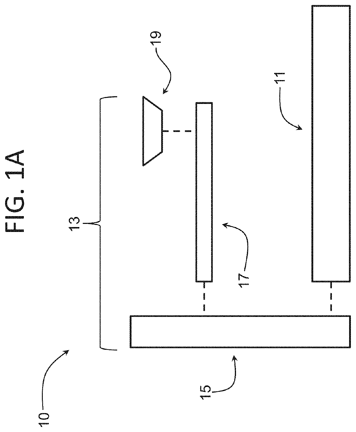
[0084]In one exemplary embodiment hereof as shown in FIG. 15, the lift assembly 13 includes a carriage and rail system 105. In one embodiment, the carriage and rail system 105 includes a carriage 106 and guide rails 108 (e.g., guide rails 108-1 and 108-2). Guide rails 108-1, 108-2 may be mounted to the frame portion 12 and configured to extend upwards. The carriage 106 may be configured with the guide rails 108-1, 108-2 and adapted to move up and down along the rails 108-1, 108-2. While FIG. 15 shows two guide rails 108-1, 108-2, the lift assembly 13 may include other numbers of guide rails 108 such as one guide rail 108, three guide rails 108 (e.g., 108-n) and other numbers of guide rails 108.

[0085]In some embodiments, the frame portion 12 may include a second transverse frame member 21 (e.g., in addition to the first transverse frame member 20) extending transversely between the first and second longitudinal frame members 16, 18 at a position in from the fir...

exemplary embodiment # 3

Exemplary Embodiment #3

[0096]In one exemplary embodiment hereof as shown in FIG. 18, the lift assembly 13 may include a carriage and rail system 105 (e.g., as described above) and associated guide rails 108-1, 108-2, transverse frame members 20, 21 and other applicable elements as required.

[0097]In one embodiment, the drive assembly 15 includes a pulley assembly 200. The pulley assembly 200 may include one or more pullies 202-1, 202-2, 202-3, . . . 202-n (collectively and individually 202), one or more cables 204 and one or more cable extenders / retractors 206 (e.g., winch).

[0098]In one embodiment, a third support member 110-3 is mounted on the first transverse support member 20 and extends upward, and fourth and fifth support members 110-4, 110-5 are mounted on the second transverse support member 21 (e.g., on the left and right portions respectively) and extend upward. It is understood that the support members 110-3, 110-4 and 110-5 may be mounted on any portion of the frame portio...


PUM


Abstract

An exercise support system configured to support at least a portion of a user's weight is disclosed. The exercise support system may include a base assembly including a plurality of frame members defining an interior region of the system. The system may also include a lift assembly comprising a drive assembly and an arm assembly. A body support (e.g., a seat) may be configured with the arm assembly. In general, the base assembly provides support to the lift assembly, and the lift assembly provides the mechanism(s) and forces to raise and lower the arm assembly (and the body support) thereby supporting at least a portion of the user's weight.

Description

CROSS REFERENCE TO RELATED APPLICATIONS[0001]This application is a continuation-in-part of U.S. patent application Ser. No. 15 / 451,049 filed Mar. 3, 2017, the contents of which are fully incorporated herein by reference for all purposes.COPYRIGHT STATEMENT[0002]This patent document contains material subject to copyright protection. The copyright owner has no objection to the reproduction of this patent document or any related materials in the files of the United States Patent and Trademark Office, but otherwise reserves all copyrights whatsoever.FIELD OF THE INVENTION[0003]This invention relates to support equipment, including equipment that supports a person's body while exercising.BACKGROUND OF THE INVENTION[0004]Supportive exercise systems can be used to provide mechanical support to assist a user with physical limitations, particularly walking and standing limitations, when performing many different kinds of exercises. The mechanical support component of such a device can protec...

Claims


Application Information

Patent Timeline
Patent Type & Authority Applications(United States)
IPC IPC(8): A63B21/068A61H3/04A63B69/00A63B21/00
CPCA63B21/068A63B69/0064A63B21/4039A63B21/158A63B22/02A63B2208/0228A63B21/00181A63B2210/50A63B24/0087A61H2201/1633A63B2208/0204A61H3/04A63B2225/09
Inventor LEFKOVITZ, JEFFREY THOMAS
Owner LEFKOTEK LLC
Why Eureka
Try Eureka