
Free ink writing instrument with microfluidic valve

Active Publication Date: 2020-07-02
SOC DITE SOC BIC
View PDF0 Cites 0 Cited by
  • Summary
  • Abstract
  • Description
  • Claims
  • Application Information

AI Technical Summary

Benefits of technology

The patent is about a microfluidic valve that only opens when the pressure inside an ink reservoir is higher than a certain level, and remains closed when the pressure is lower. This ensures that the ink stays at the desired level and prevents untimely evaporation of solvents that can damage the ink quality. Additionally, placing the valve on the cap helps to keep the ink level stable even when the cap is closed. The technical effect of this technology is to improve the quality and stability of ink in a microfluidic ink cartridge.

Problems solved by technology

An ongoing problem with free-ink writing instruments is that of avoiding evaporation of the solvents in the ink while regulating the pressure within the ink reservoir to avoid ink leakage in the region of the tip.
Thus, when the tip is protected by a cap that seals a space around the writing tip to avoid evaporation of the solvents in the ink, the baffle / porous element / fibrous element can no longer perform its pressure regulating function.
This is particularly problematic when the writing instrument is exposed to an environment that leads to significant changes in pressure between the inside and the outside of the ink reservoir, for example in an airplane or when exposed to direct sunlight in a car.
Consequently, when there is a significant change in the surrounding pressure, for example during an airplane journey, ink may leak, even in the presence of a baffle.

Method used


Image

  • Free ink writing instrument with microfluidic valve
  • Free ink writing instrument with microfluidic valve
  • Free ink writing instrument with microfluidic valve

Examples


first embodiment

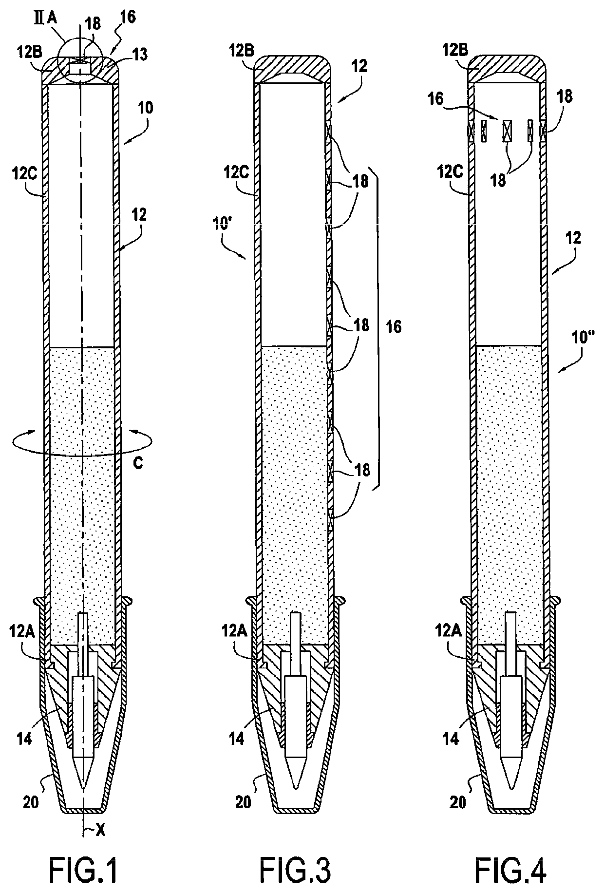
[0052]FIG. 1 shows a writing instrument 10. The writing instrument 10 comprises a main body 12 provided with a writing tip 14. In this embodiment, the main body 12 has an inner cavity and forms a free-ink reservoir 12 in which the ink 13 is free to move. Although the main body and the reservoir are formed by the same part in this embodiment, the main body and the reservoir may be formed by two separate parts in a variant.

[0053]The reservoir 12 is provided with a pressure regulating device 16 for regulating the pressure within the reservoir 12. In this embodiment, the pressure regulating device 16 comprises a single bidirectional microfluidic-valve unit 18.

[0054]It is noted that the reservoir 12 extends in an axial direction X and a circumferential direction C. The writing tip 14 is arranged at a first end 12A in the axial direction X of the reservoir 12. In this embodiment, the bidirectional microfluidic-valve unit 18 is arranged at the second end of the reservoir 12, opposite the f...

second embodiment

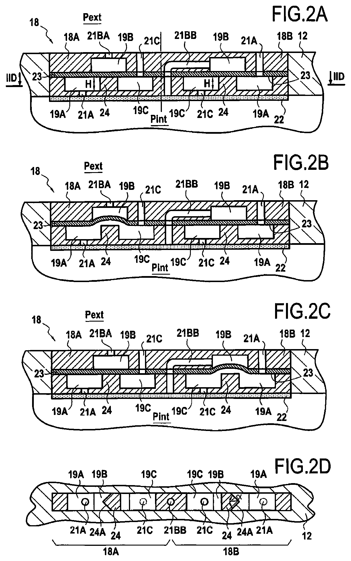
[0066]the writing instrument 10′ in FIG. 3 comprises a plurality of bidirectional microfluidic-valve units 18 evenly distributed in the axial direction X of the reservoir 12. For example, each bidirectional microfluidic-valve unit 18 is spaced apart from the adjacent bidirectional microfluidic-valve units 18 by 1 cm (one centimeter) in the axial direction X.

third embodiment

[0067]the writing instrument 10″ in FIG. 4 comprises a plurality of bidirectional microfluidic-valve units 18 evenly distributed in the circumferential direction C of the reservoir 12. For example, each bidirectional microfluidic-valve unit 18 is spaced apart from the adjacent bidirectional microfluidic-valve units 18 by 36° in the circumferential direction C, around the axis X of the reservoir 12.


PUM


Abstract

A writing instrument including a main body provided with a writing tip. The writing tip being supplied with ink by a free ink-type reservoir equipped with a pressure regulating device for regulating the pressure within the reservoir. The pressure regulating device includes at least one microfluidic valve.

Description

CROSS REFERENCE TO RELATED APPLICATION(S)[0001]This application is a National Stage Application of International Application No. PCT / FR2018 / 051410, filed on Jun. 14, 2018, now published as WO2018 / 229443 and which claims priority to French Application No. FR1755418, filed Jun. 15, 2017.FIELD[0002]The disclosure relates to the field of “free-ink” writing instruments, and more particularly to a pressure regulating device for a free-ink writing instrument.[0003]As a reminder, a “free-ink writing instrument” or a “writing instrument having a free-ink reservoir” is a writing instrument in which the ink is free to flow in the reservoir. In other words, the ink flows instantaneously from one side of the reservoir or the other, for example under the influence of gravity. In particular, the ink will be understood to be capable of moving when the writing instrument is manipulated or when the writing instrument is moved.PRIOR ART[0004]An ongoing problem with free-ink writing instruments is that...

Claims


Application Information

Patent Timeline
IPC IPC(8): B43K5/18B43K7/03
CPCB43K5/1827B43K7/03B43K7/10B43K8/04B43K8/143B43K8/18B43K23/12
Inventor ALBENGE, OLIVIERBUGE, LAUDINEDEBRAUWER, CHRISTELLEDAMIANO, ANNE-LISEEVRARD, CLAIRE
Owner SOC DITE SOC BIC
Learn More