
Biocompatible rechargable energization elements for biomedical devices with electroless sealing layers

a biomedical device and electroless sealing technology, applied in cell components, batteries, instruments, etc., can solve the problems of challenging environments for the definition of various functionalities, and achieve the effect of reducing the number of energizing elements

Inactive Publication Date: 2020-07-02
JOHNSON & JOHNSON VISION CARE INC
View PDF6 Cites 0 Cited by
  • Summary
  • Abstract
  • Description
  • Claims
  • Application Information

AI Technical Summary

Benefits of technology

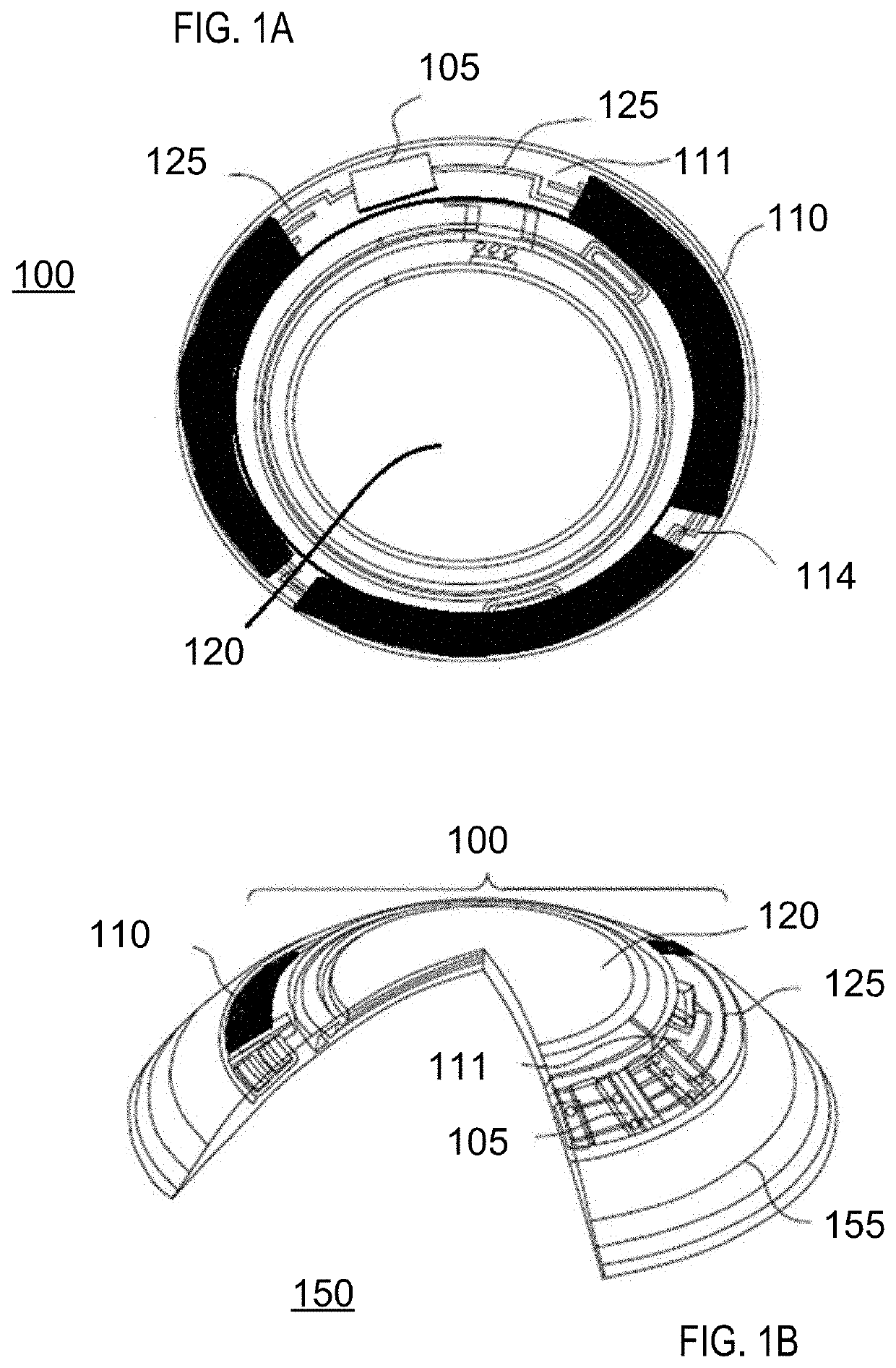
The patent describes a method and apparatus for creating biocompatible energization elements that can be used in biomedical devices such as contact lenses. The method allows for the controlled creation of structures that can contain battery chemistry, while also providing control over the amount of energy elements present. The resulting elements have a ridge of metallic coating that acts as a barrier to moisture, and can be used in multiple charging and discharging cycles. The method also allows for the creation of elements with different cathode and anode chemicals, as well as with intercalated metal atoms or other materials. The use of these elements in biomedical devices can provide improved functionality and reliability.

Problems solved by technology

However, such semiconductor components require energy and, thus, energization elements should preferably also be included in such biocompatible devices.
The topology and relatively small size of the biocompatible devices creates novel and challenging environments for the definition of various functionalities.

Method used


Image

  • Biocompatible rechargable energization elements for biomedical devices with electroless sealing layers
  • Biocompatible rechargable energization elements for biomedical devices with electroless sealing layers
  • Biocompatible rechargable energization elements for biomedical devices with electroless sealing layers

Examples


Embodiment Construction

[0022]Methods and apparatus to form three-dimensional biocompatible energization elements are disclosed in this application. The separator element within the energization elements may be formed with novel methods and may comprise novel materials. In the following sections, detailed descriptions of various embodiments are described. The description of both preferred and alternative embodiments are exemplary embodiments only, and various modifications and alterations may be apparent to those skilled in the art. Therefore, the exemplary embodiments do not limit the scope of this application. The three-dimensional biocompatible energization elements are designed for use in or proximate to the body of a living organism.

Glossary

[0023]In the description and claims below, various terms may be used for which the following definitions will apply:

[0024]“Anode” as used herein refers to an electrode through which electric current flows into a polarized electrical device. The direction of electri...


PUM

PropertyMeasurementUnit
turn-on voltagesaaaaaaaaaa
feature sizeaaaaaaaaaa
operating voltageaaaaaaaaaa

Abstract

Methods and apparatus to form biocompatible energization elements are described. In some embodiments, the methods and apparatus to form the biocompatible energization elements involve forming cavities comprising active cathode chemistry. The active elements of the cathode and anode are sealed with a laminate stack of biocompatible material. In some embodiments, a field of use for the methods and apparatus may include any biocompatible device or product that requires energization elements.

Description

CROSS REFERENCE TO RELATED APPLICATIONS[0001]This application is a divisional of U.S. patent application Ser. No. 15 / 631,446, filed Jun. 23, 2017, which in turn claims the benefit of continuation-in-part of U.S. patent application Ser. No. 14 / 746,178 filed Jun. 26, 2015, which in turn claims the benefit of U.S. Provisional Application No. 62 / 040,178 filed Aug. 21, 2014. The contents are relied upon and hereby incorporated by reference.BACKGROUND OF THE INVENTION1. Field of the Invention[0002]Methods and apparatus to form biocompatible energization elements are described herein. In some embodiments, the methods and apparatus to form the biocompatible energization elements involve forming a separator element of the energization element. The active elements including anodes, cathodes and electrolytes may be electrochemically connected and may interact with the formed separator elements. The active elements may be configured in such a manner that the battery may be discharged and rechar...

Claims


Application Information

Patent Timeline
Patent Type & Authority Applications(United States)
IPC IPC(8): H01M2/18H01M10/0569H01M4/58H01M2/14H01M4/62H01M4/587H01M4/38G02C7/04G02C11/00G02C7/08H01M4/50H01M4/04H01M4/42H01M10/04H01M6/40H01M2/02H01M4/583H01M2/16H01M10/0568H01M6/12B29D11/00H01M50/109H01M50/119H01M50/133H01M50/406H01M50/426H01M50/463
CPCH01M2300/004B29D11/00817H01M2220/30H01M2/0202H01M10/0436H01M4/386H01M4/625B29D11/00048H01M4/0402H01M10/0525H01M4/587H01M10/052H01M4/5825H01M10/0569H01M6/32H01M2/18G02C7/04H01M4/42H01M10/0568H01M6/425H01M4/583H01M2002/0205H01M6/40H01M2004/028H01M4/622H01M4/24H01M2/1653G02C7/083H01M4/50H01M2/026H01M2/145H01M6/04H01M6/12G02C11/10Y02E60/10H01M50/463Y02P70/50H01M50/133H01M50/406H01M50/109H01M50/426H01M50/119
Inventor FLITSCH, FREDERICK A.MUTHU, MILBURN EBENEZERPUGH, RANDALL B.TONER, ADAMWEINSTEIN, LAWRENCE EDWARD
Owner JOHNSON & JOHNSON VISION CARE INC
Learn More