Device for assembling a turbine engine, and method using the device

Pending Publication Date: 2020-07-23
SN DETUDE & DE CONSTR DE MOTEURS DAVIATION S N E C M A
View PDF0 Cites 2 Cited by
  • Summary
  • Abstract
  • Description
  • Claims
  • Application Information

AI Technical Summary

Benefits of technology

The patent describes a device for improving the centring and guiding of a shaft in a machine. By using a guiding tube, the device can be easily inserted without damaging the first module and can search for the second module's shaft or shaft guide to limit the swinging movements. The guiding tube ensures precise axial guiding and allows for the engagement of labyrinth seals, simplifying the handling process. Additionally, the device includes a fixed element to prevent rotation and a casing element for the first module.

Problems solved by technology

However, the LP module 3 is heavy (typically 1200 kg) and the risk of swinging and misalignment of the LP shaft 4 during docking is major.

Method used


Image

  • Device for assembling a turbine engine, and method using the device
  • Device for assembling a turbine engine, and method using the device
  • Device for assembling a turbine engine, and method using the device

Examples


Embodiment Construction

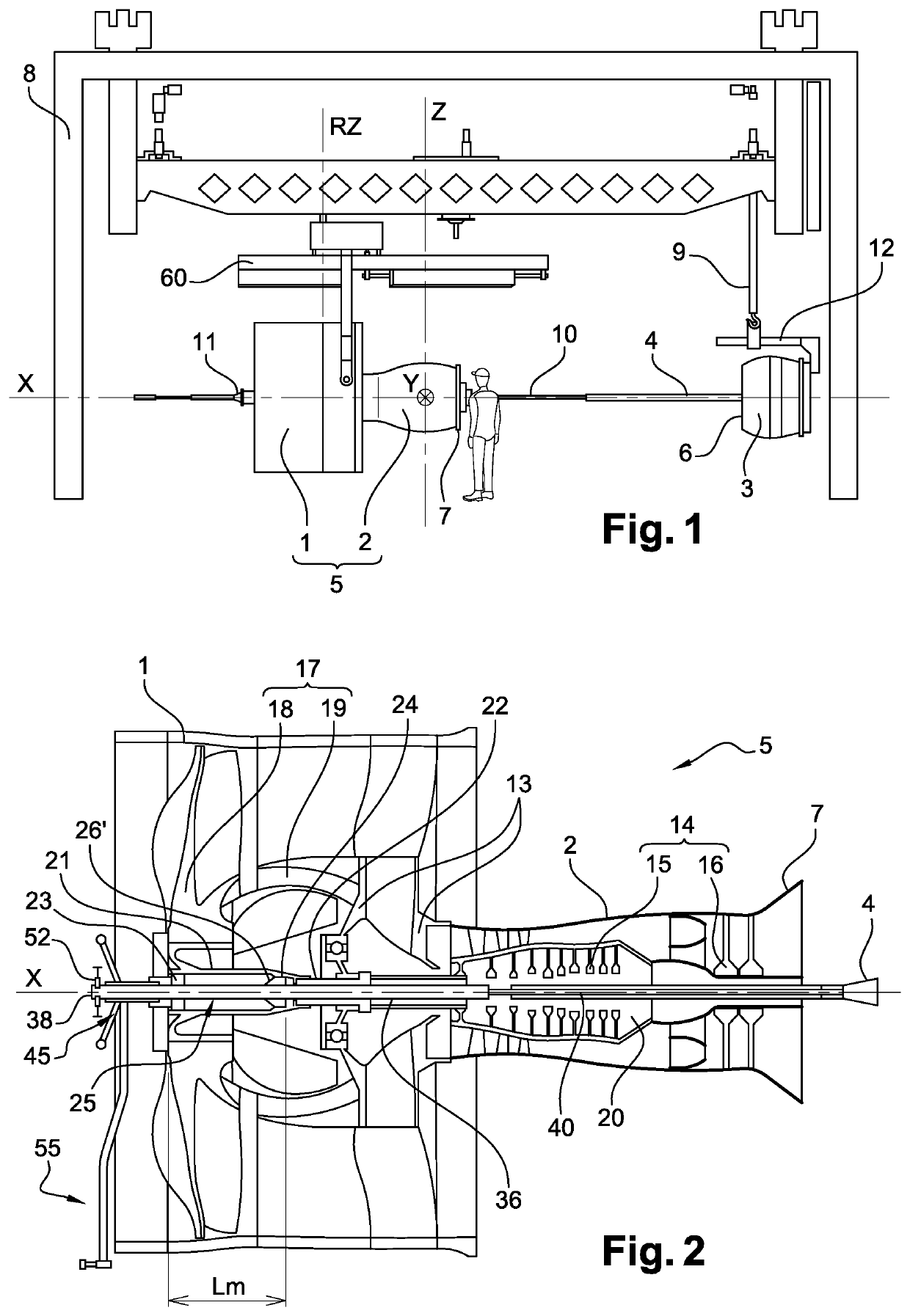
[0057]The tool according to the invention is intended to be able to be used in particular during a mounting phase illustrated in FIG. 1, already described in the introduction. Before describing the tool and the manner to use it, the type of turbine engine to which it is applied must be briefly specified.

[0058]FIG. 2 shows the first module 5 such as defined above, i.e. the upstream fan body 1 and the HP body 2 assembled, with the tool installed for a mounting phase. The first module 5 comprises a fixed structure 13, here termed the first casing, which supports the rotating portions 14 of the HP body 2, here the high-pressure compressor 15 and the high-pressure turbine 16, as well as the rotating portions 17 of the upstream fan body 1, intended to be driven by the LP shaft 4, here the fan 18 and the low-pressure compressor 19. The LP module 3 is not represented in the figure. Only the front end of the LP shaft 4 is represented, outside of the rear of the first module 5.

[0059]The eleme...


PUM

PropertyMeasurementUnit
Timeaaaaaaaaaa
Lengthaaaaaaaaaa
Forceaaaaaaaaaa

Abstract

A device for assembling a turbine engine is configured for centering a shaft of a second module relative to a longitudinal axis of a hollow hub placed in front of a first module, the first module including a longitudinal cavity opening at the front into the hollow hub and passing through the first module until a rear end, the shaft configured to be inserted into the longitudinal cavity. The device includes a centering element and a guiding tube. The centering element is configured to be placed in the hollow hub. The guiding tube is configured to enter into at least one portion of the longitudinal cavity of the first module. The device is arranged so that the guiding tube slides inside the centering element. The invention also relates to the assembly formed by the device and a calibration jig, as well as an assembly method using same.

Description

FIELD OF THE INVENTION[0001]The present invention relates to the field of turbine engines and, in particular, to multibody gas turbine engines. It relates to operations of assembling engines and in particular, to mounting the low-pressure turbine module on a high-pressure body.STATE OF THE ART[0002]The state of the art comprises, in particular, documents US-A1-2009 / 288291 and EP-A1-1 757 777.[0003]A double-body turbine engine, with a front fan for example, comprises a high-pressure body, termed HP body, and a low-pressure body, termed LP body. The LP body, downstream from the HP body, rotates at a first speed and comprises a low-pressure turbine which drives the front fan. In this document, upstream and downstream, respectively the front and the rear, are defined relative to the general direction of the flow of the gases in the turbine engine. The HP body rotates at a different speed from that of the low-pressure turbine. The shafts of the two bodies are concentric and the shaft of ...

Claims


Application Information

Patent Timeline
IPC IPC(8): B23P15/04F02C3/04
CPCF05D2230/64F02C3/04B23P15/04F01D5/025F01D5/026F01D5/066F01D25/285F04D29/644F05D2230/68
Inventor GASTAL, THIERRY FERNANDCREUSET, MORGAN BRYAN ANTONYPETIT, ERIC LOUIS CHARLES
Owner SN DETUDE & DE CONSTR DE MOTEURS DAVIATION S N E C M A
Why Eureka
Try Eureka