Coin guiding apparatus

Active Publication Date: 2005-01-27
ASAHI SEIKO CO LTD
View PDF8 Cites 1 Cited by
  • Summary
  • Abstract
  • Description
  • Claims
  • Application Information

AI Technical Summary

Benefits of technology

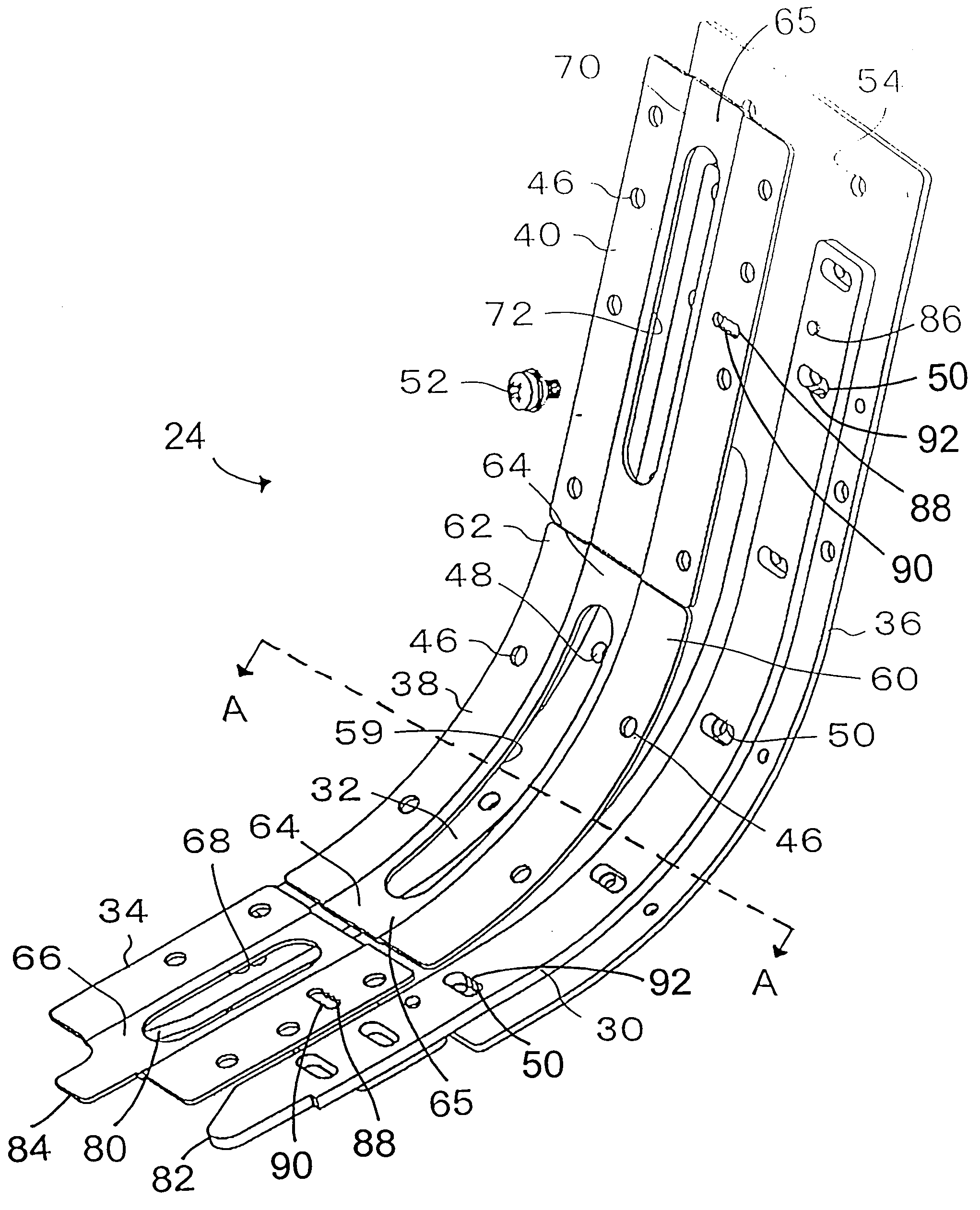
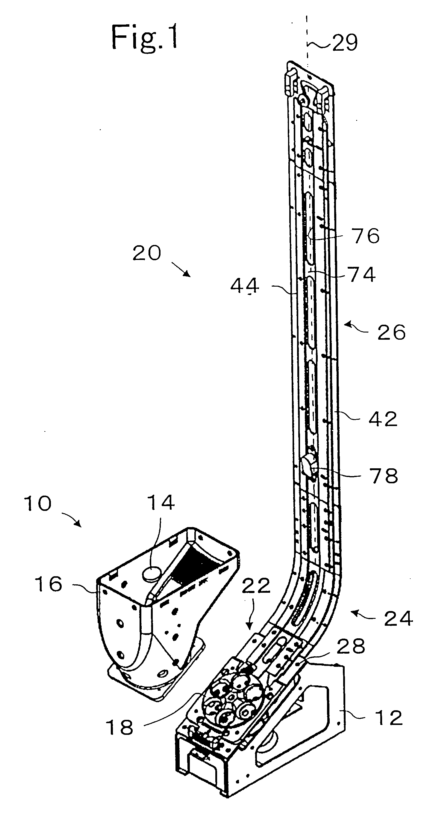
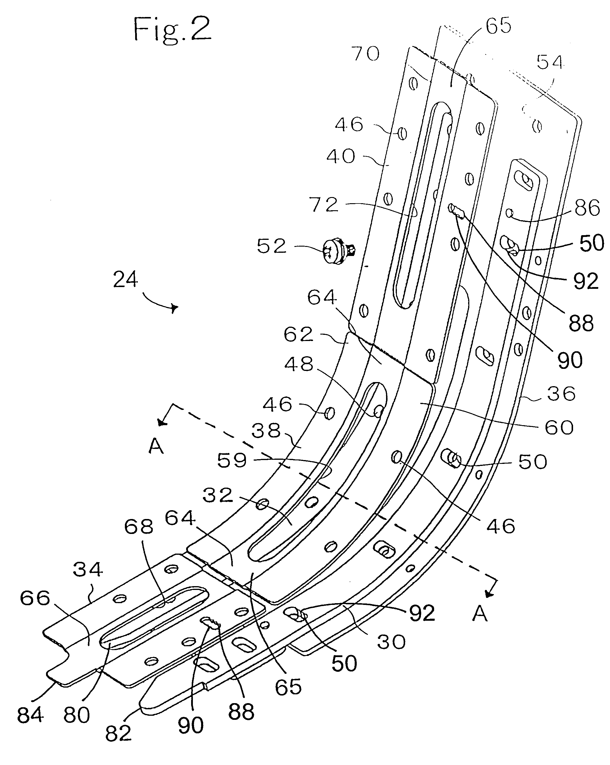
[0010] In another embodiment, a holding unit is used to prevent coins from slipping backwards along the coin guiding channel. This is especially beneficial when a portion of the coin guiding channel is oriented vertically, and the gravitational force pulling against the advancing coins is maximized. Further, for each additional coin in the coin guiding channel an incremental amount of weight, corresponding to the weight of each coin, is added as a dispensing load upon the coin hopper and a rotating dispensing disk. Although the accumulated weight of the coins must be borne at some point during dispensing and advancing the column of edge-wise oriented coins, the holding unit limits the amount of weight that must be borne continuously and avoids jamming at the dispensing point of the coin hopper unit.
[0011] In another embodiment, the supporting plate may be constructed with a wave-like structure having projections alternately towards and away from the coin guiding channel. The projections away from the coin guiding channel can be rounded in shape in order to provide increased elasticity to the supporting plate. The projections toward the coin guiding channel can be flattened in shape in order to provide a piecewise planar surface fac

Problems solved by technology

However, coin guiding passageways are prone to twisting and bending that distorts the passageway causing the jamming of coins.
Further, the coin guiding passageway wi

Method used


Image

  • Coin guiding apparatus
  • Coin guiding apparatus
  • Coin guiding apparatus

Examples


Example

[0020] Reference will now be made in detail to the preferred embodiments of the invention, examples of which are illustrated in the accompanying drawings. While the invention will be described in conjunction with the preferred embodiments, it will be understood that they are not intended to limit the invention to these embodiments. On the contrary, the intention is intended to cover alternatives, modifications and equivalents, which may be included within the spirit and scope of the invention as defined by the appended claims.

[0021] Furthermore, in the following detailed description of the present invention, numerous specific details are set forth in order to provide a thorough understanding of the present invention. However, it will be obvious to one of ordinary skill in the art that the present invention may be practiced without these specific details. In other instances, well known methods, procedures, components, and circuits have not been described in detail as not to unnecess...


PUM

PropertyMeasurementUnit
Diameteraaaaaaaaaa
Electrical resistanceaaaaaaaaaa
Shapeaaaaaaaaaa

Abstract

A coin guiding channel receives coins dispensed from a coin hopper. A base plate, a first spacer, a second spacer, and a supporting plate have surfaces defining a somewhat rectangular coin guiding channel along a longitudinal axis of the base plate. The supporting plate has a first protruding section extending toward the coin guiding channel and extending along the longitudinal axis of the base plate for providing increased strength and resistance to physical distortion of the coin guiding channel. A portion of the coin guiding channel is oriented vertically and guides the received coins to a position above the coin hopper.

Description

CROSS-REFERENCE TO RELATED APPLICATION [0001] This application is based on application number 2003-175653 filed in Japan, dated Jun. 20, 2003. FIELD OF THE INVENTION [0002] This invention is related to a coin guiding apparatus and more particularly to a coin guiding apparatus having a resistance to bending or distortion of a coin guiding channel. DESCRIPTION OF RELATED ART [0003] Traditional coin escalators, and coin hoppers dispensing coins into coin guiding passageways, are known. However, coin guiding passageways are prone to twisting and bending that distorts the passageway causing the jamming of coins. This is especially true when the coin guiding passageway is oriented vertically. Examples of the related art include the Japanese Laid Open Utility model No. 06-51957 (FIGS. 24 and pages 5-7), U.S. Pat. No. 5,662,520 to Evodokimo (FIGS. 1-2), and U.S. Pat. No. 5,558,197 to Rothschile et al. (FIGS. 2-4). [0004] Attempted solutions to these problems have included using more rigid m...

Claims


Application Information

Patent Timeline
IPC IPC(8): A61K9/70A61F13/00A61K8/02A61L15/16A61L15/58A61P17/02C09J5/08C09J7/02C09J109/00C09J153/00G07D1/00G07D9/00
CPCY10S193/01G07D9/00A61P17/02
Inventor UMEDA, MASAYOSHI
Owner ASAHI SEIKO CO LTD
Why Eureka
Try Eureka