Exhaust Hood Energy Recovery Device

Active Publication Date: 2020-07-23
PROGRESS IND LLC
View PDF0 Cites 0 Cited by
  • Summary
  • Abstract
  • Description
  • Claims
  • Application Information

AI Technical Summary

Benefits of technology

[0023]As mentioned above, the energy recovery modules are comprised of a plurality of heat pipes within a compact unit. These modules can take any shape or size provided that they are elongated and can fit within the existing kitchen hood. The inventors anticipate using a plurality of smaller energy recovery modules that can be stacked on top or beside one another. The use of smaller modules allows for a more cost effective and portable unit that can be easily removed, cleaned, and exchanged. The phrase “easily removeable” as used in this patent application shall refer to an energy recovery module that can be taken out and cleaned or inspected by a single person of average size having no specialized training. The phrase “easily exchangeable” as used in this patent application shall refer to the removal and handling of at least one energy recovery module and the installation of at least one energy recovery module by a single individual of average size having no specialized training. It should be noted that the efficiency of the energy recovery will increase with the number of energy recovery modules used. More modules can be added to the hood as the need arises or as the user's budget allows.
[0024]A sliding door or hinged panel may be added to a

Problems solved by technology

As discussed above, commercial kitchens generate large amounts of heat, harmfu

Method used


Image

  • Exhaust Hood Energy Recovery Device
  • Exhaust Hood Energy Recovery Device
  • Exhaust Hood Energy Recovery Device

Examples


Embodiment Construction

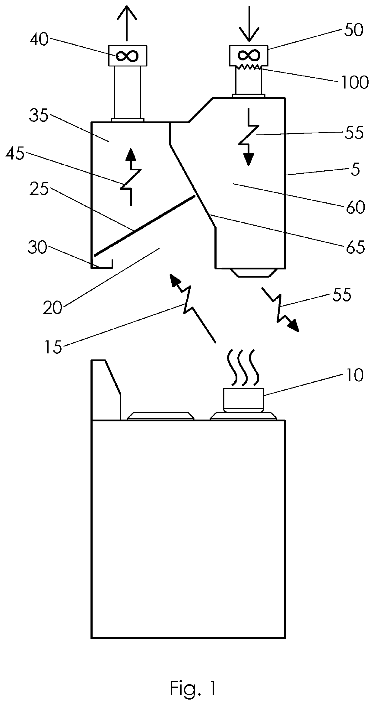
[0074]FIG. 1 illustrates a typical commercial kitchen hood 5 positioned above a cooking operation 10. In this design, hot exhaust 15 from the cooking operation 10 is drawn into the air entrance chamber 20 and through a filter 25. Excess grease drips from the filter 25 into a grease collection trough 30 while the filtered air 45 passes into the exhaust chamber 35 of the hood 5. An exhaust fan 40, creates the draft, drawing the filtered air 45 to the exterior while a makeup air unit 50 delivers fresh makeup air 55 to the supply chamber 60 of the hood. A baffle 65 separates the hot exhaust 15 and filtered air 45 from the fresh makeup air 55. The baffle 65 may be placed at any point within the kitchen hood 5 provided that the design creates acceptable air velocity flows for each air stream.

[0075]Oftentimes the fresh makeup air 55 must be heated before it is returned to the cooking area. This is typically done with heating device 100 within the makeup air unit 50. The present invention s...


PUM


Abstract

A method and apparatus for recovering energy from exhaust air in a standard kitchen ventilation hood. One or more removeable energy recovery modules comprised of a plurality of heat pipes is mounted above the hot exhaust gases. Working fluid within the heat pipes transfers heat to the makeup air, warming it before it is returned to the kitchen.

Description

CROSS REFERENCE TO RELATED APPLICATIONS[0001]This application claims benefit of priority from U.S. Provisional Patent Application No. 62 / 794,287 of William Gress and David James Gress filed Jan. 18, 2019, entitled EXHAUST HOOD ENERGY RECOVERY DEVICE, the entirety of which is incorporated herein by reference.STATEMENT REGARDING FEDERALLY SPONSORED RESEARCH / DEVELOPMENT[0002]Not ApplicablePARTIES TO A JOINT RESEARCH AGREEMENT[0003]Not ApplicableREFERENCE TO SEQUENCE LISTING, TABLE OR COMPUTER PROGRAM[0004]Not ApplicableFIELD OF THE INVENTION[0005]The present invention pertains to the extraction of energy from heated gases exhausted from a kitchen ventilation hood. The recovered thermal energy may be used to rewarm the fresh makeup air returning to the kitchen.BACKGROUND OF THE INVENTION[0006]Commercial, industrial and institutional kitchens inherently generate large amounts of heat, harmful gases and particulate that must be cleansed from the air. The process of cooking meats and oils ...

Claims


Application Information

Patent Timeline
IPC IPC(8): F24C15/20F28D15/02
CPCF24C15/2035F28D15/0275F24C15/2042F24C15/20F28D21/0008F28D2015/0216
Inventor GRESS, WILLIAMGRESS, DAVID J.
Owner PROGRESS IND LLC
Why Eureka
Try Eureka