Cable condition monitoring sensor device method

a sensor device and condition monitoring technology, applied in the field of online cable insulation condition monitoring, can solve the problems of huge economic loss, difficult to directly measure the common mode current, and the reliability of power system operation, and achieve the effect of accurately measuring the micro common mode current in the cabl

Active Publication Date: 2020-07-30
TSINGHUA UNIV
View PDF0 Cites 3 Cited by
  • Summary
  • Abstract
  • Description
  • Claims
  • Application Information

AI Technical Summary

Benefits of technology

[0037]4. It has been verified in a laboratory that the designed common mode current measurement device of the cable has measurement accuracy of 4.19% for the common mode currents of 0-1 A and has the measurement accuracy of 8.61% for the common

Problems solved by technology

Cables in operation often suffer from aging and failure due to moisture or overload, which affects the safe and reliable operation of power systems and causes huge economic loss.
However, in the cable, the common mode current is weak, the interference by a relatively high differential mode load current exists, and the cable has a complex structure and a larger cable diameter, which makes it difficult to directly measure the common mode current.
However, for the measurement of common mode currents in an electrical equipment, especially in cables, the Rogowski coil has the following obvious defects.
1. As the Rogowski coil is not specifically designed for common mode current measurement, when there is a plu

Method used


Image

  • Cable condition monitoring sensor device method
  • Cable condition monitoring sensor device method
  • Cable condition monitoring sensor device method

Examples


Embodiment Construction

[0044]In order to make the objects, technical solutions, and advantages of the present invention clearer, the present invention is described in further detail below with reference to the accompanying drawings. It should be understood that the description is merely exemplary and is not intended to limit the scope of the present invention. Moreover, in the following description, well-known structures and techniques are not described to avoid unnecessarily obscuring the concept of the present invention.

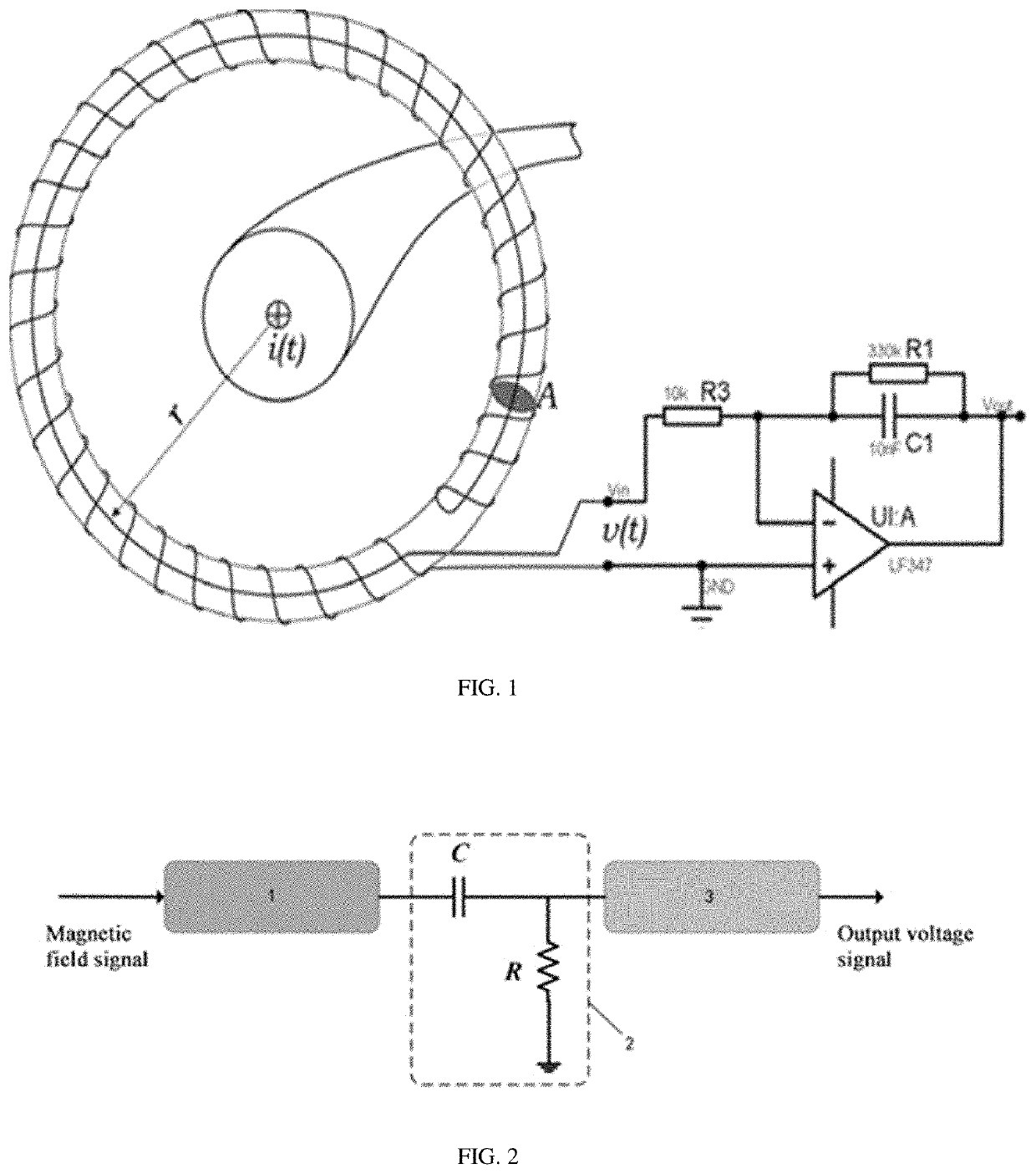
[0045]The present invention provides a cable condition monitoring sensor device. As shown in FIG. 2, the cable condition monitoring sensor device includes a TMR magnetic field sensor module 1, a high-pass filtering module 2, and a signal-amplifying module 3 which are sequentially connected. The TMR magnetic field sensor module 1 measures a magnetic field change signal of a cable, converts the same into a voltage signal, and outputs the voltage signal to the high-pass filtering module 2. ...


PUM


Abstract

A cable condition monitoring sensor device includes a TMR magnetic field sensor module, a high-pass filtering module, and a signal-amplifying module which are sequentially connected. The TMR magnetic field sensor module measures a magnetic field change signal of a cable, converts the same into a voltage signal, and outputs the voltage signal to the high-pass filtering module. The high-pass filtering module filters out DC bias of the voltage signal, and transmits the filtered voltage signal to the signal-amplifying module. The signal-amplifying module amplifies the filtered voltage signal to obtain an output voltage signal and outputs the output voltage signal. In the present invention, a common mode current to be measured in the cable is extracted by placing the magnetic shielding ring made of ferromagnetic material outside the cable to filter out a differential mode load current in the cable, and the magnitude of the common mode current is determined.

Description

CROSS-REFERENCE TO RELATED PATENT APPLICATION[0001]This application claims priority to and the benefit of CN201910976500.1, filed Oct. 15, 2019 entitled “CABLE CONDITION MONITORING SENSOR DEVICE METHOD,” by Pinjia Zhang et al. The entire disclosure of the above-identified application is incorporated herein by reference.[0002]Some references, which may include patents, patent applications, and various publications, are cited and discussed in the description of the present disclosure. The citation and / or discussion of such references is provided merely to clarify the description of the present disclosure and is not an admission that any such reference is “prior art” to the present disclosure described herein. All references cited and discussed in this specification are incorporated herein by reference in their entireties and to the same extent as if each reference was individually incorporated by reference.TECHNICAL FIELD[0003]The present invention relates to the field of on-line cabl...

Claims


Application Information

Patent Timeline
IPC IPC(8): G01R33/09G01R33/00G01R1/18
CPCG01R33/0023G01R33/098G01R1/18G01R19/0092G01R31/1272G01R15/205
Inventor ZHANG, PINJIAWU, YANG
Owner TSINGHUA UNIV
Why Eureka
Try Eureka