
Antenna Switch Diversity Circuitry

a technology of diversity circuitry and antenna switch, applied in diversity/multi-antenna system, duplex signal operation, pulse technique, etc., can solve problems such as co-channel interference and signal fading

Active Publication Date: 2020-07-30
GOOGLE LLC
View PDF3 Cites 0 Cited by
  • Summary
  • Abstract
  • Description
  • Claims
  • Application Information

AI Technical Summary

Benefits of technology

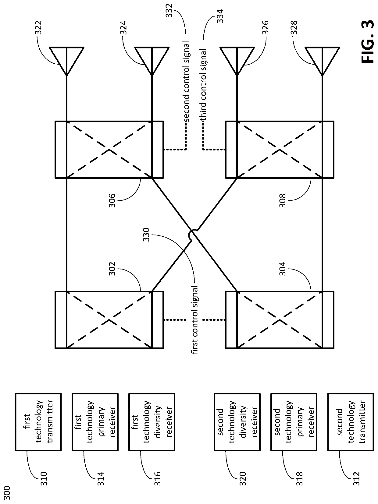
[0005]An implementation of the disclosed technologies can include a method for preventing a signal from a first transmitter and a signal from a second transmitter from being conveyed through a same switch. The first transmitter can have a first switch connected to the first transmitter. The second transmitter can have a second switch connected to the second transmitter. The first switch can have a third switch and a fourth switch connected to the first switch. The second switch can have the third switch and the fourth switch connected to the first switch. The first switch and the second switch can be controlled in a manner so as to prevent the signal from the first transmitter and the signal from the second transmitter from being conveyed through the same switch. The same switch can be the third switch or the fourth switch.

Problems solved by technology

Such a signal can be susceptible to fading, co-channel interference, or both.
Moreover, in broadband cellular network technology, antennas can be disposed at separate locations on a mobile communications device so that it is unlikely that a hand holding the mobile communications device will block all of the antennas on the mobile communications device.

Method used


Image

  • Antenna Switch Diversity Circuitry
  • Antenna Switch Diversity Circuitry
  • Antenna Switch Diversity Circuitry

Examples


Embodiment Construction

[0021]As used herein, a statement that a component can be “configured to” perform an operation can be understood to mean that the component requires no structural alterations, but merely needs to be placed into an operational state (e.g., be provided with electrical power, have an underlying operating system running, etc.) in order to perform the operation.

[0022]A diversity scheme can be a technique used to improve a reliability of a communication of a signal propagated through space as a radio wave. Such a signal can be susceptible to fading, co-channel interference, or both. The diversity scheme can provide for multiple versions of the signal to be communicated through multiple channels. So, for example, if one version of the signal is communicated through a channel that experiences a high degree of fading, but another version of the signal is communicated through a channel that does not experience a high degree of fading, then a combination of the multiple versions of the signal ...


PUM


Abstract

Antenna switch diversity circuitry can include four switches. A first switch can be connectable to a first transmitter, a first receiver, and a second receiver. A second switch can be connectable to a second transmitter, a third receiver, and a fourth receiver. A third switch can be directly connected to the first switch, the second switch, a first antenna, and a second antenna. A fourth switch directly can be connected to the first switch, the second switch, a third antenna, and a fourth antenna. The first and second switches can be configured to be controlled by a control signal in a manner so as to prevent a signal from the first transmitter and a signal from the second transmitter from being conveyed through a same switch, which can reduce a production of an intermodulation distortion signal by the signal from the first transmitter and the signal from the second transmitter.

Description

BACKGROUND[0001]A diversity scheme can be a technique used to improve a reliability of a communication of a signal propagated through space as a radio wave. Such a signal can be susceptible to fading, co-channel interference, or both. The diversity scheme can provide for multiple versions of the signal to be communicated through multiple channels. So, for example, if one version of the signal is communicated through a channel that experiences a high degree of fading, but another version of the signal is communicated through a channel that does not experience a high degree of fading, then a combination of the multiple versions of the signal by a receiver can improve the reliability of the communication of the signal.[0002]The diversity scheme can include, for example, multiple antennas to transmit and / or receive the multiple versions of the signal. Such a diversity scheme can be referred to as antenna diversity. Antenna diversity can include techniques with respect to types and arran...

Claims


Application Information

Patent Timeline
Patent Type & Authority Applications(United States)
IPC IPC(8): H04B7/06H04B7/12H04B1/48H04L5/14H03K17/693
CPCH03K17/693H04B1/48H04L5/1461H04B7/12H04B7/0602H04B7/0802H04B1/006
Inventor DAUGHERTY, JOHNNATARAJAN, VIMALKAUSHIK
Owner GOOGLE LLC
Learn More