
Conformable adhesive bandages

a technology of adhesive bandages and bandages, applied in the field of adhesive bandages, can solve the problems of affecting the blood flow to the tissue, the orientation of the bandage limbs in relation to the body of the bandage cannot be changed, and the joint motion cannot be changed

Pending Publication Date: 2020-08-06
TRU COLOR PRODN LLC
View PDF15 Cites 16 Cited by
  • Summary
  • Abstract
  • Description
  • Claims
  • Application Information

AI Technical Summary

Benefits of technology

This patent describes a type of adhesive bandage that can be easily shaped to fit different wounds. The bandage has a central body and several bandage limbs, each with an adhesive coating on one side. There are also flexible sites on the central body and the bandage limbs that allow for bending, which can be directed inward or outward. The flexible sites on the bandage limbs can also be divided into pairs, with one site on each edge of the limb. The technical effects of this design are improved flexibility, conformity to wounds, and better adhesion to the skin.

Problems solved by technology

The challenge of application of adhesive bandages around joints is their ability to remain in place despite all the surrounding skin motion associated with joint movement.
When strip bandages are applied around joints, they can significantly restrict skin motion and thus joint motion during activity, and can be uncomfortable, prone to pulling off, and may even impact blood flow to the tissue.
The disadvantage of these H-type designs, however, is that the orientation of the bandage limbs in relation to the body of the bandage cannot be changed.
This restricts the degree to which the bandage limbs are able to contour and fit the varied anatomical prominences around the joints of hands and feet.

Method used


Image

  • Conformable adhesive bandages
  • Conformable adhesive bandages
  • Conformable adhesive bandages

Examples


Embodiment Construction

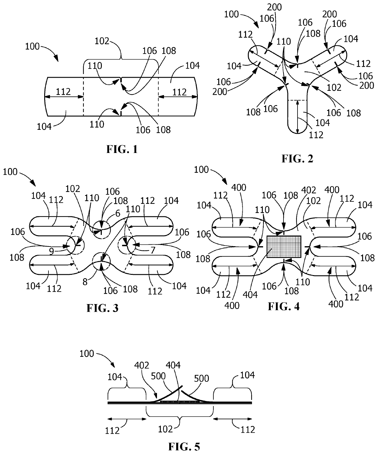
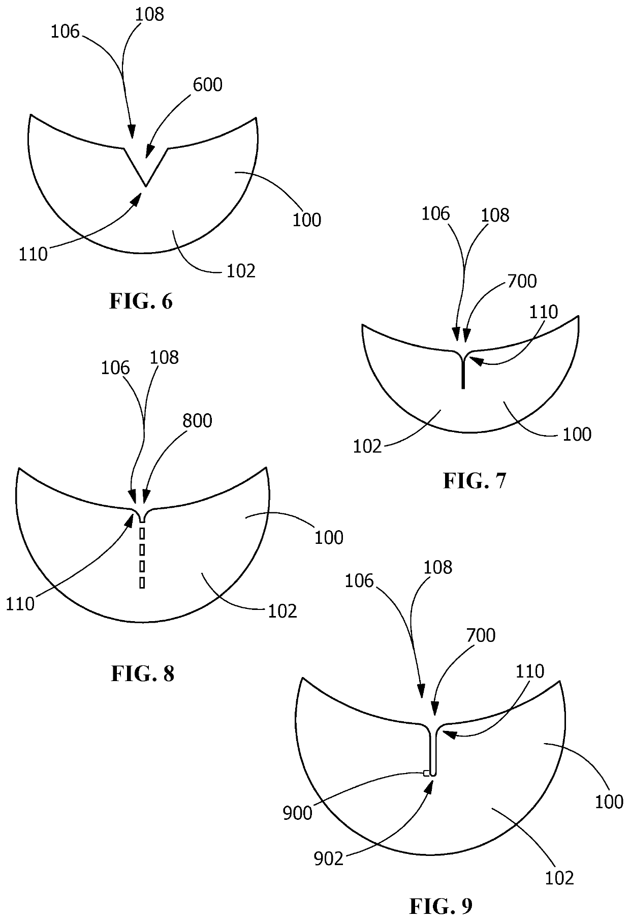
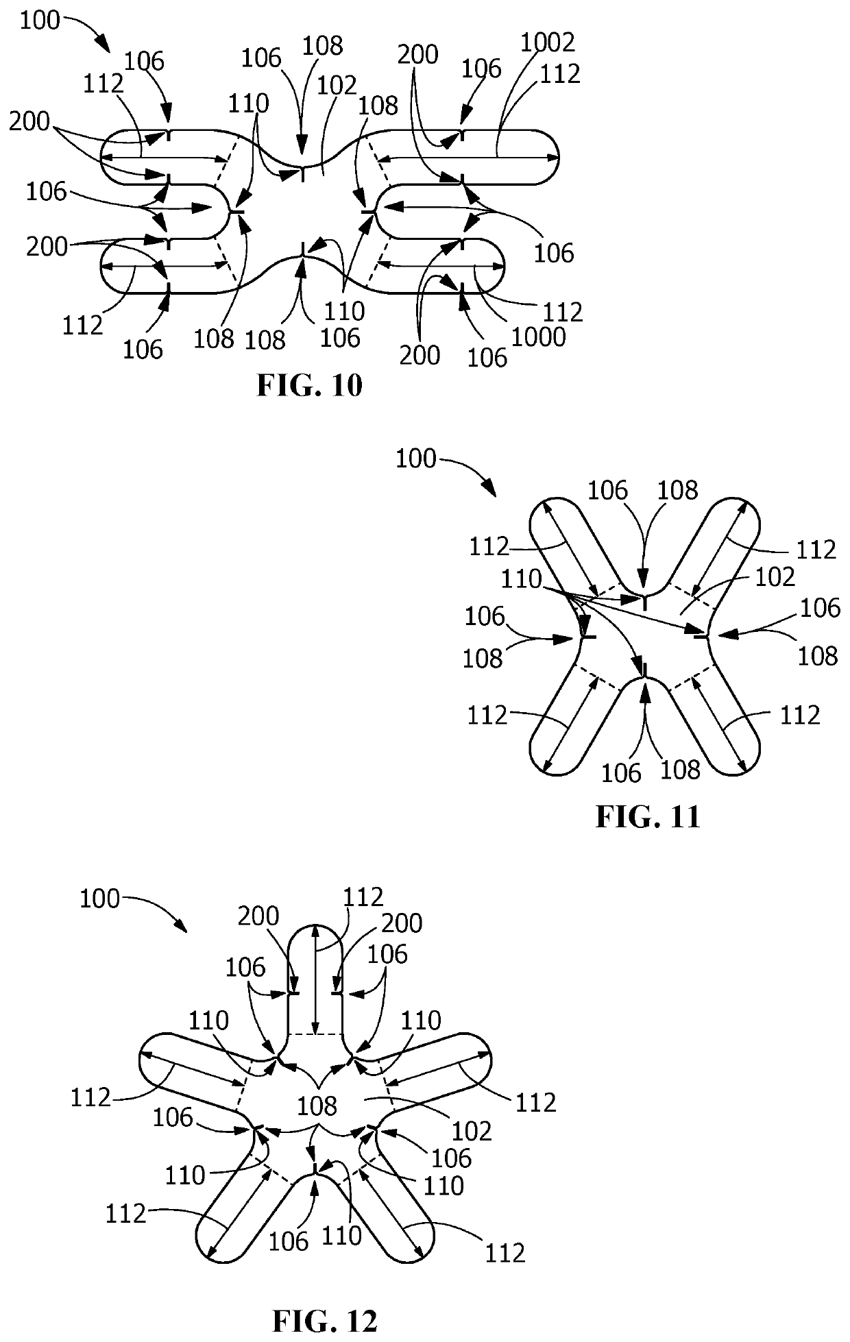
[0025]Referring to FIGS. 1-14, in one embodiment, a conformable adhesive bandage 100 includes a central body 102, a plurality of bandage limbs 104, and a plurality of flexion sites 106, each of the plurality of flexion sites 106 inflecting inward into the central body 102 or the plurality of bandage limbs 104. Referring to FIG. 4, conformable adhesive bandage 100 includes an adhesive coating 400 disposed on a first side 402 of the conformable adhesive bandage 100.

[0026]The plurality of bandage limbs 104 may include or consist of any suitable number of bandage limbs 104, including, but not limited to, two bandage limbs 104 (FIG. 1), three bandage limbs 104 (FIG. 2), four bandage limbs 104 (FIGS. 3-11, 13, and 14), five bandage limbs 104 (FIG. 12), or more. Each bandage limb 104 may be straight, curved, angled, or any combination thereof. A single conformable adhesive bandage 100 may include identical bandage limb 104 conformations, symmetric bandage limb 104 conformations, asymmetric...


PUM


Abstract

A conformable adhesive bandage is disclosed including a central body, a plurality of bandage limbs including an adhesive coating disposed on a first side of the conformable adhesive bandage, and a plurality of flexion sites, each of the plurality of flexion sites inflecting inward into the central body or the plurality of bandage limbs. In one embodiment, the plurality of flexion sites is disposed at a plurality of vertices along the central body between adjacent bandage limbs of the plurality of bandage limbs, the plurality of flexion sites inflecting radially inward at the plurality of vertices into the central body. In another embodiment, is the plurality of flexion sites includes a plurality of central body flexion sites disposed at a plurality of vertices along the central body between adjacent bandage limbs, and a plurality of bandage limb flexion sites disposed along at least one of the plurality of bandage limbs.

Description

RELATED APPLICATIONS[0001]This application claims the benefit of and priority to U.S. Prov. App. No. 62 / 800,886, filed Feb. 4, 2019, which is hereby incorporated by reference in its entirety.FIELD OF THE INVENTION[0002]This application is directed to adhesive bandages. More specifically, this application is directed to adhesive bandages inducing reduced restriction of joint motion relative to non-inventive adhesive bandages.BACKGROUND OF THE INVENTION[0003]The challenge of application of adhesive bandages around joints is their ability to remain in place despite all the surrounding skin motion associated with joint movement. Adhesive bandages that are currently used to cover minor wounds around joint areas of upper and lower extremities consist of an adhesive cloth fabric, with absorbent central pad. Most bandages have a simple wide strip design.[0004]When strip bandages are applied around joints, they can significantly restrict skin motion and thus joint motion during activity, and...

Claims


Application Information

Patent Timeline
Patent Type & Authority Applications(United States)
IPC IPC(8): A61F13/02
CPCA61F13/0259A61F2013/00544A61F13/025A61F13/0206
Inventor WURAPA, RAYMOND K
Owner TRU COLOR PRODN LLC
Learn More