Turbo fan engine

a technology of turbine engine and fan engine, which is applied in the direction of engines, mechanical equipment, clutches, etc., can solve the problems of increasing airframe weight, increasing weight, and generating excess thrust for parked aircraft, so as to improve idle rating, improve fuel efficiency, and increase the effect of airframe weigh

Active Publication Date: 2020-08-20
IHI CORP
View PDF0 Cites 3 Cited by
  • Summary
  • Abstract
  • Description
  • Claims
  • Application Information

AI Technical Summary

Benefits of technology

[0029]According to the turbo fan engine of the present disclosure, the power to operate the starter generator as the generator is constantly extracted from the low-pressure shaft and is not extracted from the high-pressure shaft. Accordingly, the high-pressure compressor does not cause surging at the low rating. Further, deterioration of fuel efficiency and increase of the airframe weight are not caused by change of the design for securement of the surge margin of the high-pressure compressor and setting of the higher idle rating. Moreover, since only the high-pressure shaft is driven by the starter generator that operates as the electric motor at startup, adoption of a large starter generator having extremely large electric motor output is not requested, and increase of the airframe weight is avoidable, unlike the turbo fan engine disclosed in Patent Document 1.

Problems solved by technology

As a result, thrust excess for the parked aircraft is generated.
To maintain the stop state of the aircraft, a brake having a large size is requested, which increases the airframe weight.
Further, to increase the rotational speed of each of the high-pressure shaft and the low-pressure shaft to the above-described state, a large starter generator having extremely large electric motor output is to be adopted, which also causes weight increase.

Method used


Image

  • Turbo fan engine
  • Turbo fan engine
  • Turbo fan engine

Examples


Embodiment Construction

[0040]An embodiment of the present disclosure is described in detail below with reference to drawings.

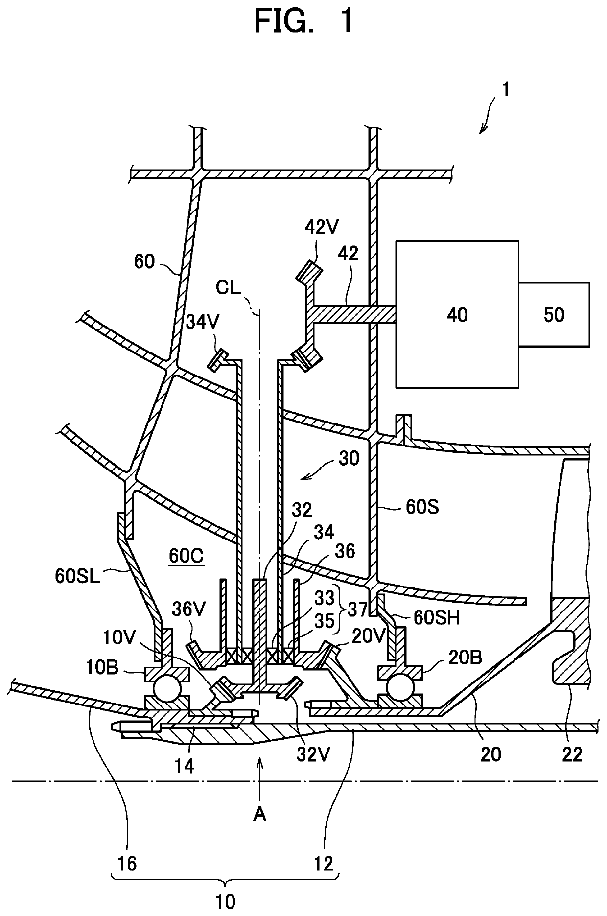
[0041]FIG. 1 is an enlarged cross-sectional view illustrating a main part of a two-spool turbo fan engine including a power transmission device according to the embodiment of the present disclosure.

[0042]A turbo fan engine 1 according to the embodiment of the present disclosure includes a low-pressure shaft (a first main shaft) 10, a high-pressure shaft (a second main shaft) 20, a power transmission device 30, an AGB 40, and a starter generator 50.

[0043]The low-pressure shaft 10 includes a fan drive shaft 12 that is connected to a rotor (not illustrated) of a low-pressure turbine on a rear side (right side in the figure), and a fan shaft 16 that is connected to a rotor (not illustrated) of a fan at a front end part. The fan drive shaft 12 and the fan shaft 16 are connected to each other by a spline coupling 14 that can transmit torque while allowing relative movement in an axial dir...


PUM


Abstract

Provided is a turbo fan engine (TF) provided with a power transmission device that switches main shafts (MSs) connected to a starter generator (SG) so as to perform power transmission, between at startup and after the startup. The TF includes a first MS and a second MS. The power transmission device includes a first shaft, an intermediate shaft, and a second shaft that are coaxially disposed, and a clutch. The first shaft is connected to the first MS through bevel gears, the intermediate shaft is disposed outside of the first shaft and is connected to the SG through bevel gears, and the second shaft is disposed outside of the intermediate shaft and is connected to the second MS through bevel gears. When, out of any two adjacent shafts of the first shaft, the intermediate shaft, and the second shaft, an inner shaft tries to rotate at a speed higher than a speed of an outer shaft, the clutch causes the both shafts to engage with each other and to rotate at the same speed, and transmits power, whereas when the outer shaft tries to rotate at a speed higher than a speed of the inner shaft, the clutch causes the both shafts to disengage from each other, and does not transmit power.

Description

TECHNICAL FIELD[0001]Embodiments described herein relate to a turbo fan engine. More specifically, the embodiments described herein relate to a turbo fan engine provided with a power transmission device that has a function to switch a main shaft supplied with power from a starter generator at startup and a main shaft supplying power to the starter generator after the startup.BACKGROUND ART[0002]A turbo fan engine includes a fan that is disposed on a frontmost part and a core engine that is disposed coaxially with the fan on a rear side of the fan.[0003]In a case of a two-spool turbo fan engine, the core engine includes a low-pressure compressor, a high-pressure compressor, a combustor, a high-pressure turbine, and a low-pressure turbine in order from a front side (upstream side) toward a rear side (downstream side). A rotor of the high-pressure turbine rotatably drives a rotor of the high-pressure compressor through a high-pressure shaft. A rotor of the low-pressure turbine rotatabl...

Claims


Application Information

Patent Timeline
Patent Type & Authority Applications(United States)
IPC IPC(8): F02C7/36
CPCF02C7/36F05D2240/60F05D2220/323F05D2260/4031F02C7/268F02C7/275F02C7/32F05D2260/403F16D41/066F16D41/12F16D2041/0665Y02T50/60
Inventor OYAMA, AKIHIKOMORIOKA, NORIKOSEKI, NAOKI
Owner IHI CORP
Why Eureka
Try Eureka