Image generating system, image generation method, control apparatus, and control method

Active Publication Date: 2020-08-20
CANON KK
View PDF0 Cites 0 Cited by
  • Summary
  • Abstract
  • Description
  • Claims
  • Application Information

AI Technical Summary

Benefits of technology

The present invention proposes a new method for generating a virtual viewpoint image using a plurality of camera groups. By determining reference times for different groups of cameras and controlling them to capture images at the determined times, a virtual viewpoint image with a frame rate equal to or higher than that of a individual camera can be generated. This allows for smoother and more stable virtual viewpoint image production.

Problems solved by technology

However, the number of cameras that can be installed is limited from the viewpoints of restrictions on the installation location and cost.
For example, when an image capturing area is not wide, there is a possibility that it is unnecessary to divide the capturing into a plurality of camera groups, and as a result, there is a problem that the capturing by the plurality of camera groups is not effectively used.

Method used


Image

  • Image generating system, image generation method, control apparatus, and control method
  • Image generating system, image generation method, control apparatus, and control method
  • Image generating system, image generation method, control apparatus, and control method

Examples


first embodiment

[0025]The first embodiment illustrates an image generating system that performs capturing by two camera groups and generates a virtual viewpoint image. The image generating system according to the first embodiment improves the frame rate of the obtained virtual viewpoint image by varying the reference time (image capturing time) of each camera group.

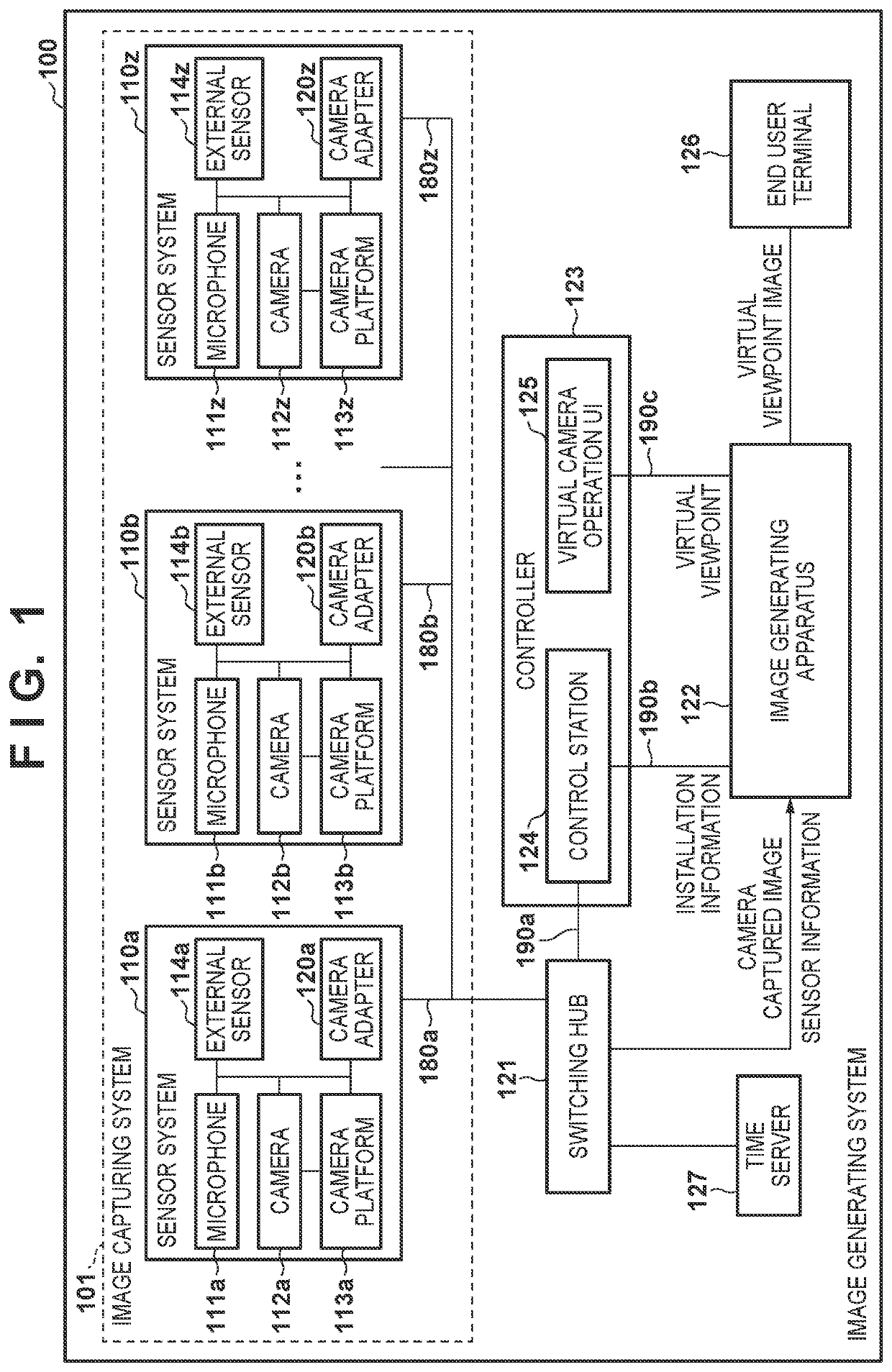
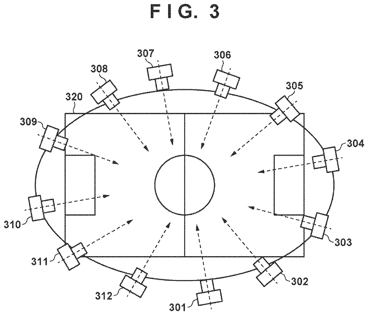
[0026]FIG. 1 is a block diagram illustrating an example of a configuration of an image generating system according to a first embodiment. The image generating system generates a virtual viewpoint image by image capturing and audio collection using a plurality of cameras and microphones installed in a sports field (stadium) or a facility such as a concert hall. Hereinafter, an image generating system according to the first embodiment will be described with reference to FIG. 1.

[0027]An image generating system 100 includes sensor systems 110a to 110z, an image generating apparatus 122, a controller 123, a switching hub 121, an end user term...

second embodiment

[0065]The second embodiment will be described with reference to the drawings. The second embodiment is an example in which a user can arbitrarily change the frame rate of the virtual viewpoint image by setting the frame rate. Note that the configuration of the image generating system according to the second embodiment is similar to that of the first embodiment (FIG. 1).

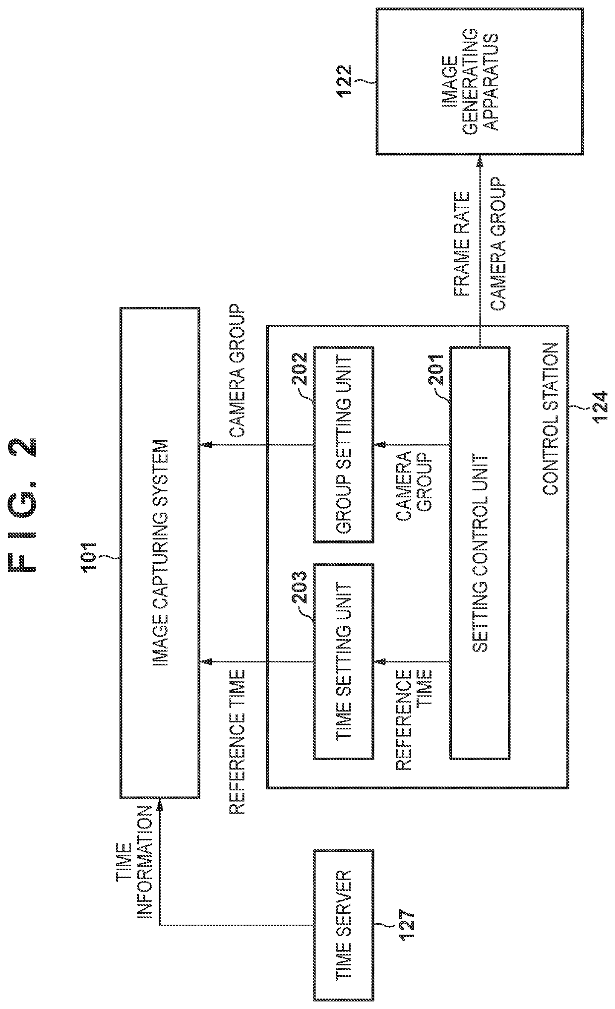
[0066]FIG. 9 is a block diagram illustrating an example of a functional configuration of the control station 124 according to a second embodiment. Functional blocks similar to those of the first embodiment (FIG. 2) are given the same reference numerals. In FIG. 9, a user setting receiving unit 901 is an interface for accepting a user instruction from, for example, the virtual camera operation UI 125 at the control station124. In the second embodiment, the user setting receiving unit 901 accepts, from the user, the frame rate of a virtual viewpoint image to be generated.

[0067]Next, processing for setting the frame rate...


PUM


Abstract

A control station manages a set of a plurality of camera groups to which a plurality of cameras belong, determines respectively different reference times for the plurality of camera groups, and controls the plurality of cameras such that the cameras that respectively belong to the plurality of camera groups execute capturing according to the determined reference times.

Description

BACKGROUND OF THE INVENTIONField of the Invention[0001]The present invention relates to an image generating system that generates a virtual viewpoint image using captured images from a plurality of cameras, an image generation method, a control apparatus, and a control method.Description of the Related Art[0002]Recently, attention has been paid to a technique in which a plurality of cameras are installed at different positions to perform synchronous capturing from multiple viewpoints, and virtual viewpoint content is generated using a plurality of images obtained by the capturing. According to the technique of generating virtual viewpoint content from a plurality of images, for example, a highlight scene for soccer or basketball can be viewed from various angles, so that a user can be given a high sense of presence as compared with a normal image. Such virtual viewpoint content is generated by aggregating images captured by a plurality of cameras to an image generating apparatus suc...

Claims


Application Information

Patent Timeline
IPC IPC(8): H04N5/247H04N5/232
CPCH04N5/23216H04N5/247H04N5/23203G01B11/245H04N23/60H04N23/90H04N23/62H04N23/66
Inventor SAKAKIMA, EITO
Owner CANON KK
Why Eureka
Try Eureka