Earth observation satellite information routing system

a satellite information and routing system technology, applied in the field of satellite information routing system, can solve the problems of only transferring information, unable to securely route sensitive information through potentially hostile neighboring territories, and delaying the warning to residents, so as to achieve the effect of securely transmitting captured information, quick and reliable transmission

Active Publication Date: 2020-09-03
CLOUD CONSTELLATION CORP
View PDF0 Cites 7 Cited by
  • Summary
  • Abstract
  • Description
  • Claims
  • Application Information

AI Technical Summary

Benefits of technology

[0009]Therefore, there exists a continuing need for a new and improved solution (the Earth Observation Satellite Information Routing System) that can quickly, reliably, and securely transmit captured information from an Earth observation satellite to a ground station nearly anywhere in the world.

Problems solved by technology

Placing an Earth observation satellite in a non-geostationary orbit, the satellite can monitor many different areas of the world with a single set of sensors; however, these satellites can only transfer information to the ground-based recipients when the satellite's orbit takes the satellite over and within range of an authorized and linked ground station.
For example, a conventional Earth observation satellite monitoring ocean levels cannot alert its operators of a tidal wave or storm until the satellite passes within range of an associated ground station (rarely positioned in the middle of the Ocean), delaying the warning to residents.
Similarly, operators of military or intelligence satellites may either prefer not to route or be incapable of securely routing sensitive information through potentially hostile neighboring territories.
If a small country is limited to only retrieve information from an intelligence satellite while the satellite traverses the sky over that small country, there is a very narrow window, and the satellite may only occasionally cross over the country every few orbits.
This orbital relationship both limits the total amount of information transferred on each pass (limited by both communication bandwidth and communication time) and delays the receipt of potentially critical security information.
The inventors here have recognized that there are definite drawbacks that significantly impact the operational value of conventional Earth observation satellites.

Method used


Image

  • Earth observation satellite information routing system
  • Earth observation satellite information routing system
  • Earth observation satellite information routing system

Examples


Embodiment Construction

[0020]The features, aspects and advantages are described below with reference to the drawings, which are intended to illustrate but not to limit the invention. It should be understood, however, that the teachings herein are not limited to any particular satellite purpose and are applicable to satellites used for other purposes, in other orbits, and in other combinations.

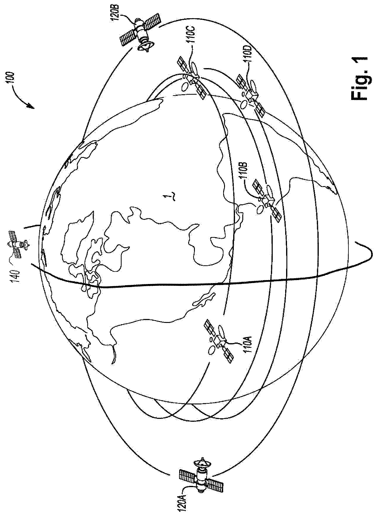
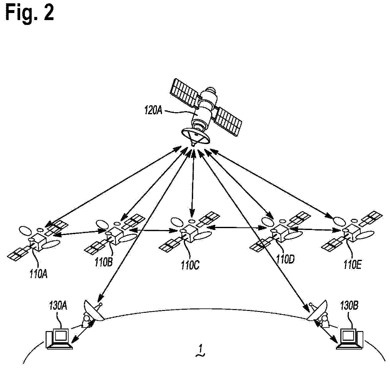
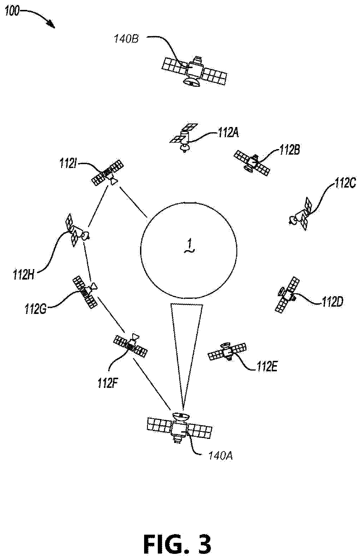
[0021]The Earth Observation Satellite Information Routing System includes one or more Earth observation satellites 140, a satellite cloud network 100 comprised of a plurality of network satellites 110 orbiting a planet 1 (e.g., the Earth), and one or more terrestrial access points 130. The Earth Observation Satellite Information Routing System may further comprise geostationary communications satellites 120.

[0022]Each network satellite 110 may include a processor 201, a memory 202, a data storage element 203, a TT&C System 204, a power system 205 (including a battery 206 and power source 207), a communications array ...


PUM


Abstract

The focus of the present disclosure relates to a constellation of earth-observation satellites communicating with terrestrial access points through an intermediate satellite constellation of networked relay satellites. The network system includes one or more terrestrial access points, one or more earth observation satellites, and a satellite constellation including a plurality of communicatively coupled relay satellites. The earth observation satellites establish links with the relay satellites, which relay the communications from the earth observation satellites to the terrestrial access points. The earth observation satellite can transfer recorded information to one or more of the plurality of relay satellites. The communication from the earth observation satellite may be routed through multiple relay satellite in the network system to reach the terrestrial access point. Rather than transferring information from an earth observation satellite only when the earth observation satellite passes over the terrestrial access point, the network disclosed enables earth observation satellites to transfer information through the intermediate satellite constellation quickly and securely from nearly anywhere along its orbit around the Earth. Because the Earth observation satellite can route recorded information through the plurality of satellites in the intermediate satellite constellation to a terrestrial access point, instead of only when the earth observation satellite travels within range of a single terrestrial access point, the disclosed network system significantly extends the data transfer window while reducing monitoring delays.

Description

INCORPORATION BY REFERENCE TO RELATED APPLICATIONS[0001]This patent application is a continuation of PCT Application No. PCT / US19 / 22157 titled “EARTH OBSERVATION SATELLITE INFORMATION ROUTING SYSTEM” and filed Mar. 13, 2019, which claims priority to U.S. provisional Application No. 62 / 642,005, titled “EARTH OBSERVATION SATELLITE INFORMATION ROUTING SYSTEM” and filed Mar. 13, 2018. This patent application additionally incorporates by reference the following applications: U.S. patent application Ser. No. 15 / 225,826, titled “SPACE-BASED ELECTRONIC DATA STORAGE AND TRA7NSFER NETWORK SYSTEM” and filed Aug. 2, 2016, International Application No. PCT / US16 / 16467, titled “SPACE-BASED ELECTRONIC DATA STORAGE AND TRANSFER NETWORK SYSTEM” and filed Feb. 3, 2016, U.S. Provisional Application No. 62 / 111,600, titled “SkyCloud Autonomous Electronic Data Storage and Information Delivery Network System” and filed Feb. 3, 2015, and PCT / US16 / 30276, titled “INTERMEDIARY SATELLITE NETWORK FOR CROSS-STRAP...

Claims


Application Information

Patent Timeline
Patent Type & Authority Applications(United States)
IPC IPC(8): B64G1/10B64G1/24H04B7/185H04B7/195
CPCH04B7/195H04B7/18521B64G1/1021B64G1/1085B64G1/242B64G1/1007B64G3/00
Inventor KAEN, HOOSHANG
Owner CLOUD CONSTELLATION CORP
Why Eureka
Try Eureka