Vacuum inlet valve assembly with a closeable seal

a vacuum inlet valve and seal technology, applied in the direction of suction hoses, household applications, suction cleaners, etc., can solve the problems of increasing the cost of the system, requiring considerable storage space and inconvenience, and the relative length of the hos

Active Publication Date: 2020-09-10
H P PROD
View PDF0 Cites 2 Cited by
  • Summary
  • Abstract
  • Description
  • Claims
  • Application Information

AI Technical Summary

Benefits of technology

[0010]In yet another aspect, an embodiment of the present disclosure may provide a method for a closure flap on a vacuum inlet valve housing comprising: removing a vacuum hose from a vacuum inlet valve housing, wherein the housing has central longitudinal axis; pivoting a closure flap about a pivot axis between an open first position and a closed second position; and wherein the closure flap is offset from the central longitudinal axis in the open first position and the closure flap intersect the central longitudinal axis in the closed second position. This exemplary method or another exemplary method may further provide compressing a protrusion on the closure flap when the closure flap is pivoting between the open first position and the closed second position; and expanding the protrusion to fit within a recess formed in the vacuum inlet valve housing when the closure flap is in the closed second position to releaseably lock the closure flap in the closed second position. This exemplary method or another exemplary method may further provide wherein the protrusion is formed from a resilient material that permits expansion and compression thereof, and wherein the closure flap's weight is insufficient to overcome a rigidity of the resilient material when nested within the recess, further comprising: imparting a force through physical manipulation to the closure flap that overcomes the rigidity of the resilient material to compress the protrusion while moving between the open first position and the closed second position. This exemplary method or another exemplary method may further provide wherein imparting a force is accomplished by pulling on a pull tab coupled in a cantilevered manner to a major surface on the closure flap. This exemplary method or another exemplary method may further provide positioning, when the closure flap is in the open first position, the protrusion lower than a concave frontal surface on the vacuum inlet valve housing. This exemplary method or another exemplary method may further provide sealing an open end defined by a lower end of a conduit of the vacuum inlet valve housing with a tapered wall on the closure flap.

Problems solved by technology

These prior system hoses have a relative length, for example 25 feet, and require considerable storage space and inconvenience for the user to retrieve it and then subsequently replace it in the storage area after a cleaning operation.
Many homeowners will buy a second or third hose for storage in a closet or other storage area adjacent each of the inlet valves thereby increasing the cost of the system.

Method used


Image

  • Vacuum inlet valve assembly with a closeable seal
  • Vacuum inlet valve assembly with a closeable seal
  • Vacuum inlet valve assembly with a closeable seal

Examples


Embodiment Construction

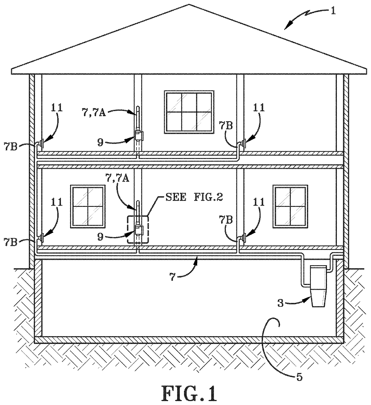
[0033]The central vacuum cleaning system of the present disclosure is indicated generally at 1 and is shown in FIG. 1. A central vacuum source 3 is located within a usual structure such as in a lower level 5 of a dwelling or could be located outside closely adjacent thereto, such as in a garage. A plurality of vacuum source tubes or conduits 7 extend from vacuum source 3 to various locations or rooms within the structure. The number of conduits will depend upon the size of the house, number of rooms, size of the vacuum source, and other factors. These vacuum supply conduits are usually formed of rigid plastic and in accordance with the present disclosure include a conduit 7A connected to a primary inlet valve indicated generally at 9, and by conduits 7B to a pair of secondary inlet valves indicated generally at 11, two of which are shown in FIG. 1 in the first floor of the dwelling and two in the top floor, the purpose of which is discussed further below.

[0034]Primary inlet valve 9 ...


PUM


Abstract

A closure flap on a vacuum inlet valve assembly or housing pivots between an open first position and a closed second position. When the closure flap is in the open first position, it is offset from a central longitudinal axis of the vacuum inlet valve housing. When the closure flap is in the closed second position, it intersects the central longitudinal axis. The closure flap has a resilient and compressible protrusion that releasable locks the closure flap in each position.

Description

CROSS REFERENCE TO RELATED APPLICATIONS[0001]This application claims the benefit of U.S. Provisional Application Ser. No. 62 / 813,278, filed on Mar. 4, 2019; the disclosure of which is incorporated herein by reference.TECHNICAL FIELD[0002]The present disclosure relates to a vacuum inlet valve assembly for a central vacuum cleaning system. The vacuum inlet valve assembly includes a closure flap that pivots between an open position and a closed position after a hose has been disconnected from the vacuum inlet valve assembly for subsequent connection with a secondary vacuum inlet valve.BACKGROUNDBackground Information[0003]Central vacuum cleaning systems for home and commercial use have been used for many years, examples of which are shown in U.S. Pat. Nos. 2,943,698, 3,520,725, 3,173,164, and 7,010,829. These systems generally are comprised of a main vacuum source, which is usually mounted in the basement or other location in the structure or closely adjacent thereto. The vacuum source...

Claims


Application Information

Patent Timeline
Patent Type & Authority Applications(United States)
IPC IPC(8): A47L9/24A47L5/38
CPCA47L5/38A47L9/242
Inventor NIESCHWITZ, DARRELL V.CALDERONE, GREG A.METZ, SHAWN C.
Owner H P PROD
Why Eureka
Try Eureka