Wire Management System with Flexible Tab

Active Publication Date: 2020-09-17
FRAM TRAK IND
View PDF0 Cites 0 Cited by
  • Summary
  • Abstract
  • Description
  • Claims
  • Application Information

AI Technical Summary

Benefits of technology

This patent is about a flexible entry tab for a wire management system that allows for easy replacement of cables after installation. The tab is removed when the adhesive is applied and re-attached after the cable is inserted. This system is simple to use and gives a streamlined appearance to the attachment of cables to surfaces.

Problems solved by technology

It is known that electrical the cords of domestic appliances such as clocks and lamps are unsightly and generally hang or run loosely from the appliances to the electrical outlets in a room.

Method used


Image

  • Wire Management System with Flexible Tab
  • Wire Management System with Flexible Tab
  • Wire Management System with Flexible Tab

Examples


Embodiment Construction

[0013]Reference will now be made in greater detail to a preferred embodiment of the invention, an example of which is illustrated in the accompanying drawings. Wherever possible, the same reference numerals will be used throughout the drawings and the description to refer to the same or like parts.

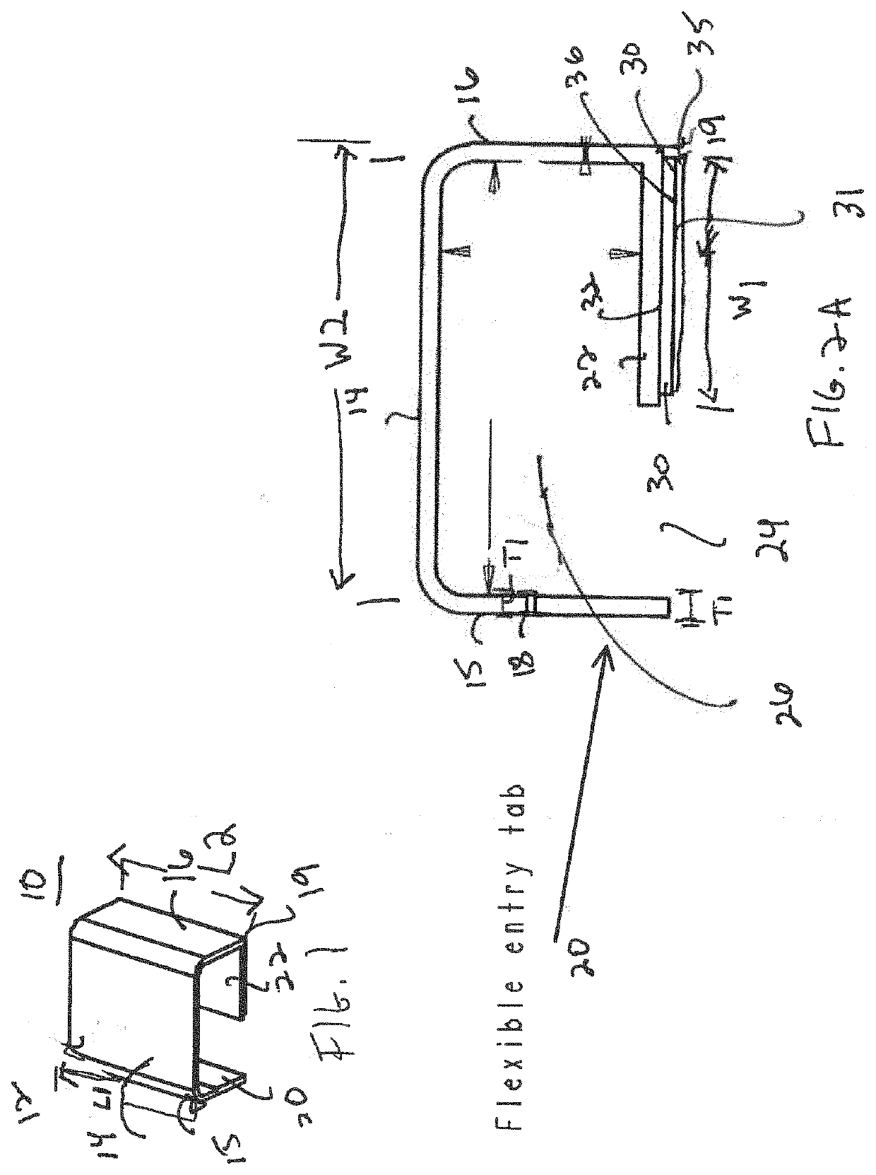
[0014]FIG. 1 is a perspective view of wire management system 10. Cord cover 12 includes front wall 14 coupled or integral with side wall 15 and side wall 16. Side wall 15 and side wall 16 can extend rearwardly from front wall 14. In one embodiment, side wall 15 and side wall 16 can extend perpendicular to front wall 14. End 18 of side wall 15 is attached or integral with flexible entry tab 20. Side wall 15 is coupled or integral to flexible entry tab 20 along the length L1 of side wall 15.

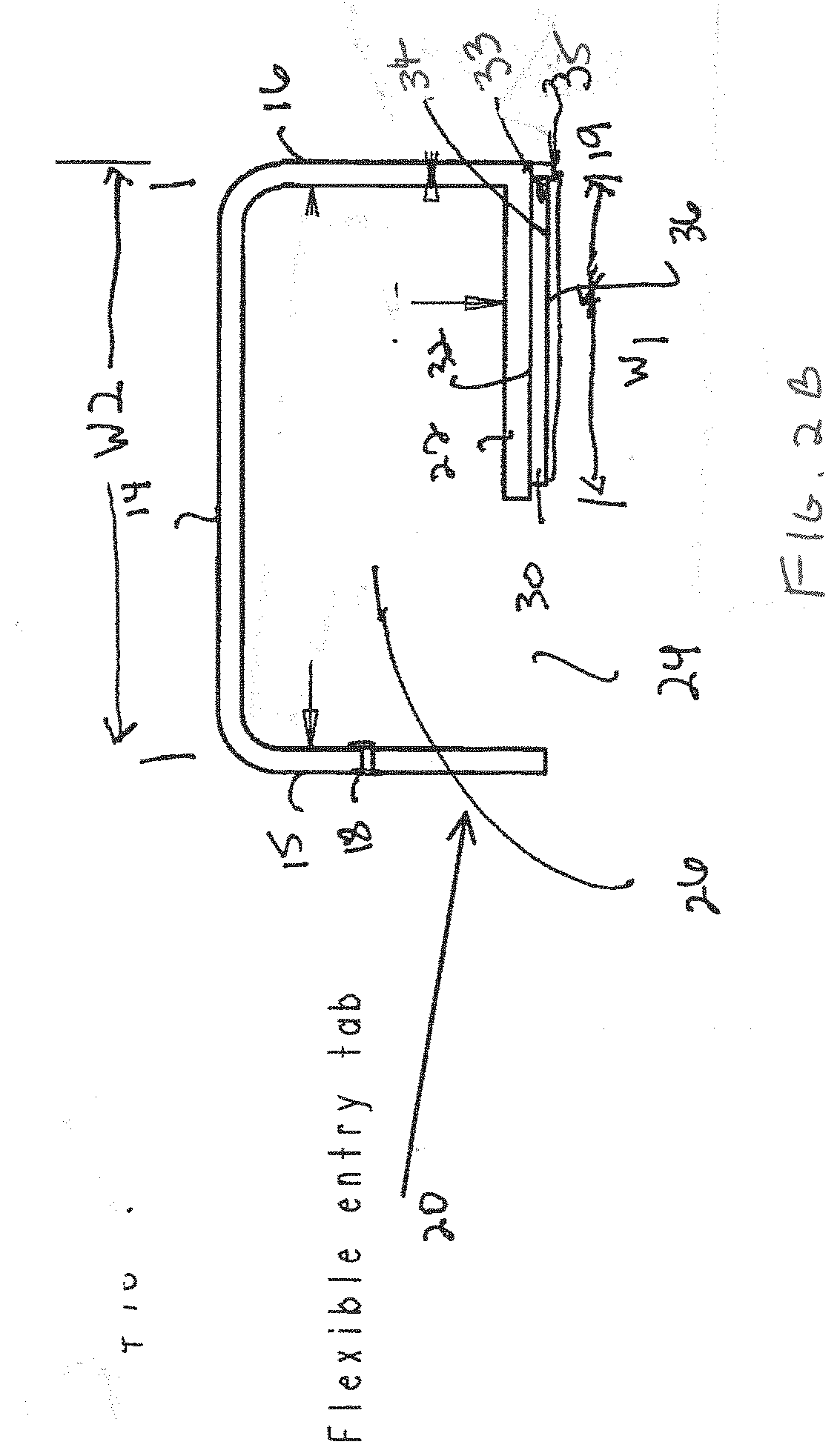
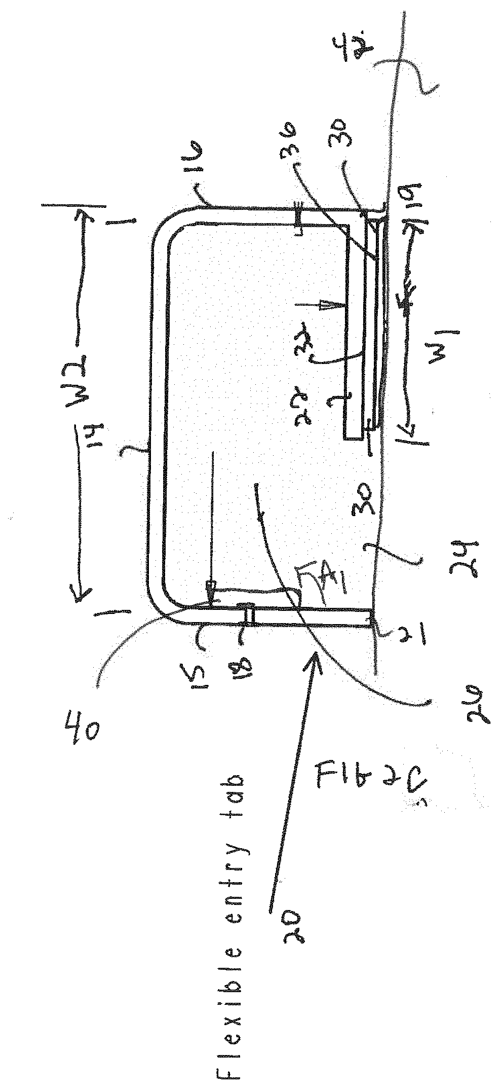
[0015]Flexible entry tab 20 extends in the same plane from side wall 15 as shown in FIG. 2A. Flexible entry tab 20 can have the same or similar thickness Ti as side wall 15. End 19 of side wall 16 is coup...


PUM


Abstract

A wire management system including a cord cover. The cord cover includes a front wall coupled or integral with two side walls. A flexible entry tab is formed at an end of one of the side walls. An end of the other of the side walls is coupled or integral to a rear wall extending laterally from the side wall. The width of the rear wall can be less than the width of the front wall to form an opening between the rear wall and the opposed side wall. A cavity is formed between the front wall, side walls and rear wall. An adhesive material or adhesive strip is attached to an outer surface of the rear wall for attachment of the cord cover to a surface. The flexible tab can be flexed for inserting a cord or wire and automatically returns to the same plane as the side wall for providing a streamlined appearance of the cord cover.

Description

BACKGROUND OF THE INVENTIONField of the Invention[0001]The present invention relates in general to an electric wire holder for hiding a received wire and in particular to a wire management system including a flexible tab.Description of Related Art[0002]It is known that electrical the cords of domestic appliances such as clocks and lamps are unsightly and generally hang or run loosely from the appliances to the electrical outlets in a room. U.S. Pat. No. 4,454,374 describes an electric cord holder, which includes a sheath made of an elongated plastic extrusion having a slotted-tubular cross-section so as to define a cord-receiving channel therein. The sheath has a dome-shaped front wall having two ends and a planar rear wall joined to one end of the front wall and extending from the one end of the front wall towards the other end of the front wall. The rear wall has a free end leaving a slot adapted for insertion of an electrical cord into the cord-receiving channel between the free ...

Claims


Application Information

Patent Timeline
IPC IPC(8): H02G3/04B65D63/10
CPCB65D63/10H02G3/0437H02G3/0418H02G3/0431
Inventor SANTELLI, JR., ALBERT
Owner FRAM TRAK IND
Why Eureka
Try Eureka