
Adjustable Knee Brace

a knee brace and adjustable technology, applied in the field of knee braces, can solve the problems of pain and discomfort, less isolative properties, and more limited mobility or immobility, and achieve the effects of enhancing mechanical advantage, facilitating knee brace adjustment, and increasing mechanical advantag

Active Publication Date: 2019-10-03
HEIBERG ERIC
View PDF0 Cites 2 Cited by
  • Summary
  • Abstract
  • Description
  • Claims
  • Application Information

AI Technical Summary

Benefits of technology

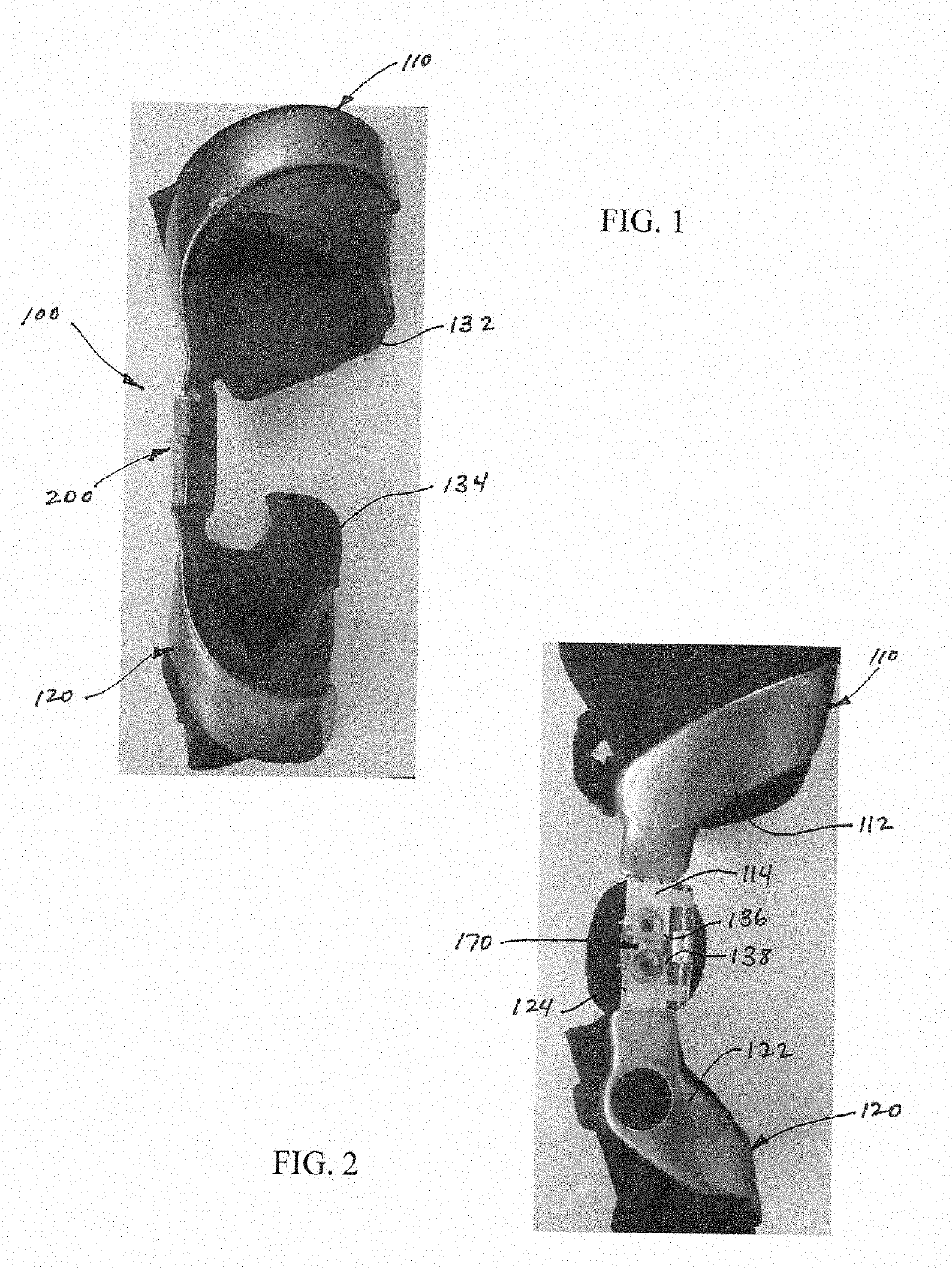
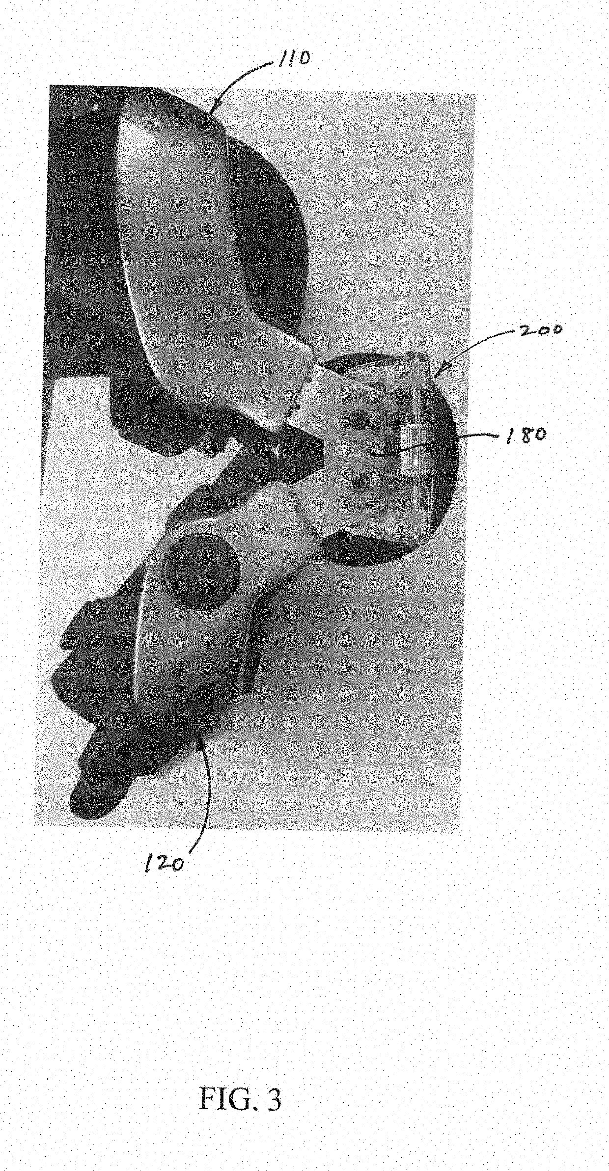
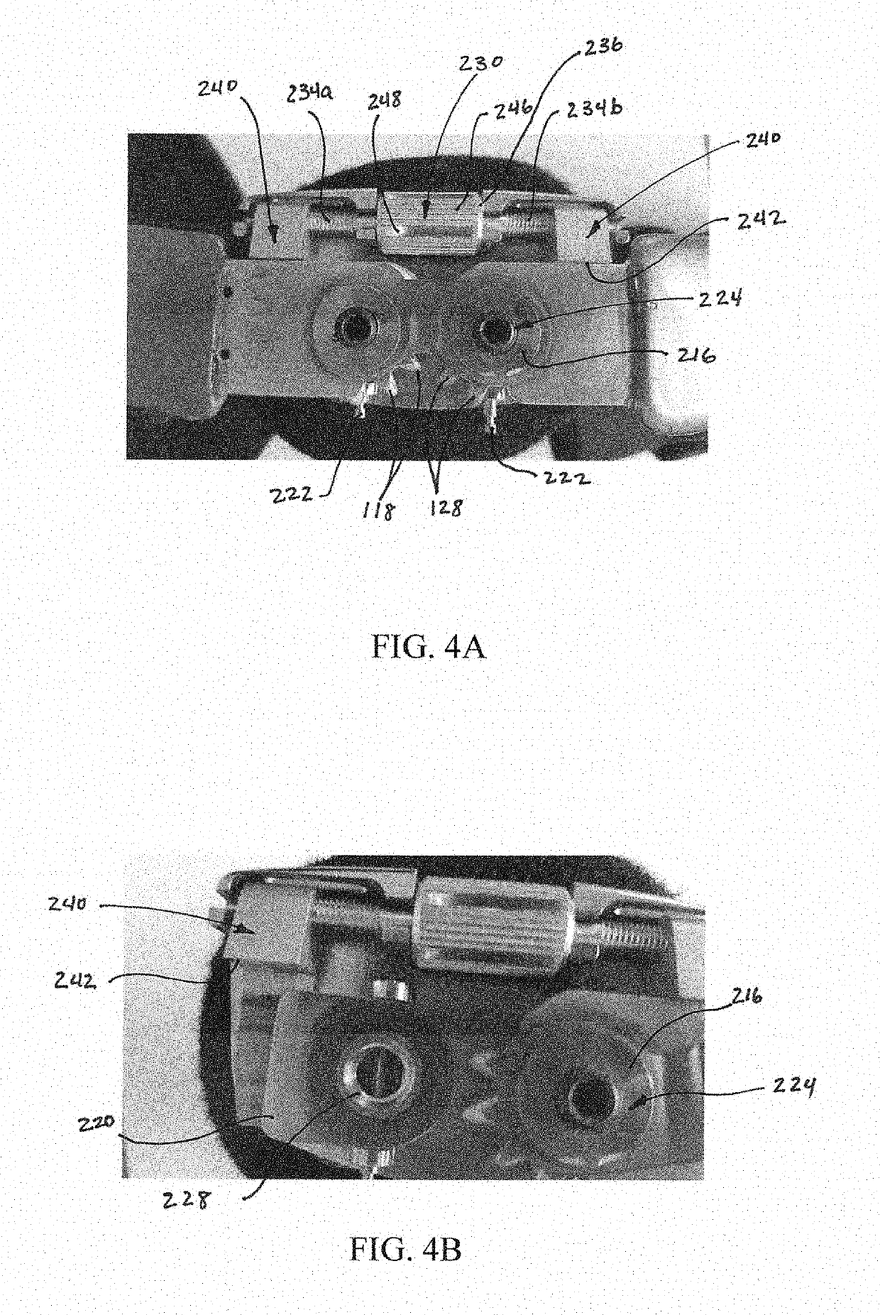
The present invention provides a knee brace that can be adjusted to change the biomechanics of the knee joint in a way that reduces pain and discomfort. The brace has a low-profile design that allows it to be worn beneath clothing and provides maximum pain relief and comfort. The brace is easily adjustable without special tools or training, and it can be adjusted to provide the minimum or maximum amount of unloading as needed by the wearer. The brace is also designed to be adjusted over an infinite number of settings between the end points of the adjustment range, allowing for optimal comfort and pain relief.

Problems solved by technology

Degradation of these critical components results in functional degradation of the knee joint which, in turn, results in pain and discomfort, and possibly more limited mobility or immobility.
Over time, the cartilage and / or meniscus may degrade and / or be damaged, resulting in a decrease in the isolative properties they are intended to provide.
For example, osteoarthritis is a degenerative disease that can affect the knee joint, and that can result in wearing away of the articular cartilage over time.
When the articular cartilage is damaged, degraded or no longer present on the femur, that can negatively affect the corresponding meniscus, and can ultimately lead to painful direct bone-on-bone contact between the femur and tibia.
However, knee braces provided in accordance with the teachings of the prior art require significant space between the knee brace and the knee to enable sufficient movement of the condyle pad.
Separate adjustment of the top and bottom of the condyle pad is not possible with this configuration, and the points of connection for the condyle pad may be generally parallel with but are not coaxial with the rotation axis of the knee brace.
This results in a knee brace having a larger profile at the knee joint, which may result in patients having to wear this brace outside of their clothing.
Consequently, knee braces according to at least these prior art documents tend to take up a significant amount of space when worn, usually requiring that the brace be worn outside one's clothes.

Method used


Image

  • Adjustable Knee Brace
  • Adjustable Knee Brace
  • Adjustable Knee Brace

Examples


Embodiment Construction

[0071]The following describes exemplary embodiments of the present invention. It should be apparent to those skilled in the art from the disclosure provided herein that the described embodiments of the present invention are illustrative and not limiting, having been presented by way of example only. All features disclosed in this description may be replaced by alternative features serving the same or similar purpose, unless expressly stated otherwise. Therefore, numerous and various other embodiments are contemplated as falling within the scope and spirit of the present invention. In addition, embodiments of the present invention comprising similar features and structure may be described singularly (e.g., description of an upper cuff without a corresponding description of a similar lower cuff). It will be obvious to persons skilled in the art, and from the disclosure provided herein, that such discussion and description of a first feature or structure is intended to, and does cover ...


PUM


Abstract

A knee brace comprising an articulation assembly connectable with a first cuff movable with respect to the articulation assembly about a first location defining a first pivot axis between the first cuff and articulation assembly, and movable about a second location defining a first rotation axis between the first cuff and articulation assembly. The knee brace may further comprise a second cuff connectable with the articulation assembly, the second cuff is movable with respect to the articulation assembly about a third location defining a second pivot axis between the second cuff and articulation assembly, and is movable about a fourth location defining a second rotation axis between the second cuff and articulation assembly. The first pivot axis and first rotation axis may intersect each other or be offset from intersecting each other, the second pivot axis and second rotation axis may intersect each other or be offset from intersecting.

Description

FIELD OF THE INVENTION[0001]The present invention is directed to a knee brace having improved design, construction, functional and aesthetic features.BACKGROUND OF THE INVENTION[0002]A human knee joint is comprised of three compartments: 1) suprapatellar pouch and patellofemoral joint (includes the patella, patellofemoral joint, the trochlear notch of the femur, and synovial plicae); 2) medial (includes the medial femoral condyle, the medial tibia plateau, and the medial meniscus); and 3) lateral (includes the lateral femoral condyle, the lateral tibial plateau, and the lateral meniscus). Although a complicated joint, the various compartments and components of a healthy knee joint simply need to isolate the femur and tibia bones from contacting each other, and facilitate smooth movement between them. To this end, articular cartilage on the medial and lateral condyles of the femur, and on the tibial plateau, together with medial and lateral meniscus, serve to isolate the femur and ti...

Claims


Application Information

Patent Timeline
Patent Type & Authority Applications(United States)
IPC IPC(8): A61F5/01
CPCA61F5/0123A61F2005/0134A61F2005/0139A61F2005/0174A61F5/0102A61F2005/0132
Inventor HEIBERG, ERIC
Owner HEIBERG ERIC
Learn More