Manual control device of the opening and closing of the lock of a door or window

Inactive Publication Date: 2020-10-01
LECLERCQ PASCAL
0 Cites 3 Cited by

AI-Extracted Technical Summary

Problems solved by technology

The pre-assembling of the handle, owing to the fact that it requires specific tools, can be delicate and not immediately achievable, at least whenever the necessary tools are not immediately available...

Benefits of technology

[0022]The same functions can thus be carried out with a reduced number of components.
[0023]The...

Abstract

The manual control device to open and close the lock of a door or window has a support body having a longitudinal cavity; a rotatable manual gripping member having a housing; a control rod engaged in the cavity of the support body; at least one quick blocking element of the axial extraction of the support body from the control rod, the support body having an end in the manual gripping member rigidly engaged in the housing and an end external of the gripping member. A support plate of the support body fixable to the door or window and having a hole to rotatably engage the external end of the support body. An angular position indexer of the manual gripping member, the indexer having a blocking seat and a one snap-fitting member engaged in the blocking seat, the blocking seat or snap-fitting member being formed integrally with the support body.

Application Domain

Building locksHandle fasteners

Technology Topic

EngineeringMechanical engineering +1

Image

  • Manual control device of the opening and closing of the lock of a door or window
  • Manual control device of the opening and closing of the lock of a door or window
  • Manual control device of the opening and closing of the lock of a door or window

Examples

  • Experimental program(1)

Example

DETAILED DESCRIPTION OF THE DRAWINGS
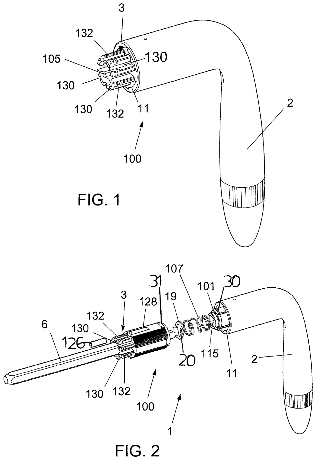
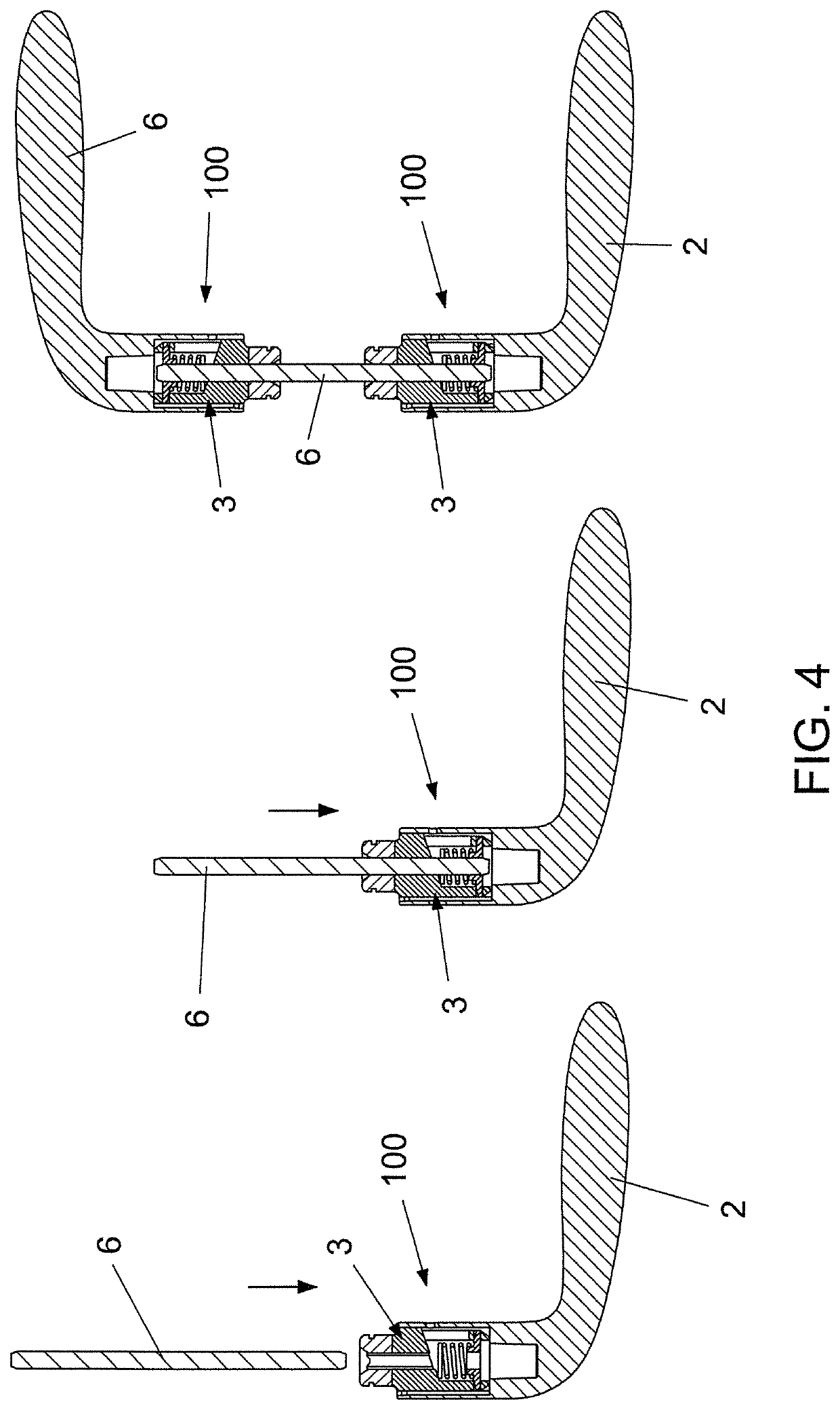
[0040]The control device 1 comprises a control rod 6 or lock control follower (not shown) arranged through a transversal hole 7 of the leaf 5, and two identical parts 100, one engaged with the section of the control rod 6 projecting from the right side of the leaf 5 and the other one engaged with the section of the control rod 6 projecting from the left side of the leaf 5.
[0041]In any case the control device can also have a single part 100, where the actuation of the lock is requested only on one side of the leaf 5.
[0042]Reference will now be made to every single part 100.
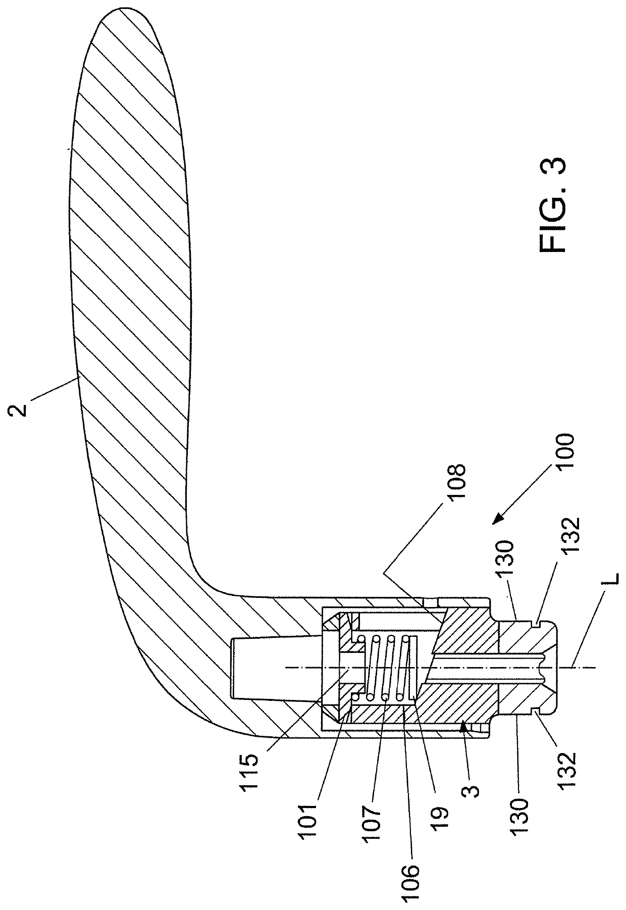
[0043]The part 100 comprises a longitudinal support body 3 longitudinally having a cavity 105 through which the control rod 6 is arranged, a rotatable manual gripping member 2 having a housing 11, and at least one quick blocking element of the axial extraction of the support body 3 from the control rod 6.
[0044]The manual gripping member 2 can be, as shown, in the form of a handle or also a knob.
[0045]The quick blocking element comprises one or more laminated springs 19 stacked on one another. The support body 3 has an end internal of the manual gripping member 2 rigidly engaged in the housing 11 and an end external of the manual gripping member 2.
[0046]The cross section of the axial cavity 105 of the support body 3 has a shape matching with the cross section of the control rod 6.
[0047]The control rod 6 is friction-engaged with the laminated spring 19 and with an insert 101 of the support body 3 adapted to increase the force opposing the axial sliding of the control rod 6 along the cavity 105 of the support body 3.
[0048]The support body 3 has a compartment 106 in which the laminated spring 19 is housed, which laminated spring 19 is flexible in opposition to and by action of an elastic element 107, in particular a coil spring 107.
[0049]The compartment 106 is delimited by a front wall 108 that is inclined to the axis of the support body 3, and opens posteriorly of the support body 3 for introduction of the laminated spring 19, the coil spring 107 and the insert 101.
[0050]The laminated spring 19 has an internal port 20 having a shape matching with the cross section of the control rod 6. The laminated spring 19 is fixed at only one side thereof to the front wall 108 in order to be able to flex. The angle between the lie plane of the laminated spring 19 and the lie plane of the front wall 108 of the compartment 106 creates a space usable for accommodating the strain of the laminated spring 19 necessary for blocking and unblocking the control element 6 inserted through the internal port 20.
[0051]The insert 101 is fixed in the support body 3 and more precisely has peripheral fins 30 fitted in suitable through-openings 31 passing through the thickness of the side wall of the support body 3.
[0052]The insert 101 can preferably be made of rubber, for example silicone rubber, or other elastically-yielding material. The insert 101 has an axial hole 115 in which the control rod 6 can be inserted by friction sliding.
[0053]The insert 101 can also be made of a closed-cell foamed material.
[0054]To fix the manual gripping member 2 to the support body 3, two independent manual fixing systems are provided, one preventing the relative rotation between the parts and the other one preventing mutual extraction of the parts.
[0055]In particular, in order to prevent the relative rotation between the manual gripping member 2 and the support body 3, one or more anti-rotation members are provided, each formed by a protrusion 124 of the external surface of the support body 3 engaged in a complementarily-shaped recess 125 formed on the internal surface of the housing 11 or vice versa.
[0056]The control rod 6, the support body 3 and the manual gripping member 2 are thus integral in rotation about a rotation axis L.
[0057]In order to prevent the relative extraction between the manual gripping member 2 and the support body 3, one or more dowels 126 are provided, each engaged in a corresponding hole 127 delimited by matching grooves 128, 129 of the external surface of the support body 3 and the internal surface of the housing 11.
[0058]The two independent systems that cooperate for fixing the manual gripping member 2 to the support body 3 are both manual and thus enable carrying out the fixing operation directly on the site of installation, the installer receiving the disassembled simple components having the opportunity of carrying out the customized finishings before assembly.
[0059]The part 100 further provides a plate 120 for supporting the support body 3 fixed to the wall of the leaf 5, for example by means of screws 121.
[0060]The support plate 120 is provided with a hole 123 in which the external end of the support body 3 is rotatably engaged.
[0061]The external end of the support body 2 has an external peripheral groove 132 in which an anti-extraction elastic ring 133 is arranged to prevent extraction of the support body 3 from the hole 123 of the support plate 120.
[0062]The part 100 finally comprises indexing means of the angular position of the manual gripping member 2.
[0063]The indexing means comprise one or more blocking seats 130 and one or more snap-fitting members 131, each engageable by snap-fitting in a corresponding blocking seat 130. Each snap-fitting member 131 is elastic, or is in turn biased by an elastic element.
[0064]The blocking seats 130 or snap-fitting members 131 are advantageously formed integrally with the support body 3.
[0065]In particular, in the illustrated case, the blocking seats 130 are afforded in one-piece with the support body 3.
[0066]The blocking seats 130 are distributed along the external periphery of the external end of the support body 3, and more precisely are formed by variations in the thickness of the wall of the external end of the support body 3 which form depressions.
[0067]The blocking seats 130 are more precisely arranged symmetrically with respect to the axis of the support body 3 and are distributed in pairs that are diametrically aligned with respect to the axis of the support body 3.
[0068]The snap-fitting members 131 are arranged about the external end of the support body 3 and preferably, as shown, are distributed in pairs that are diametrically aligned with respect to the axis of the support body 3.
[0069]The snap-fitting members 131 are arranged and configured so as to slide along the external periphery of the external end of the support body 3 when the support body 3 is set in rotation.
[0070]The snap-fitting members 131 in the illustrated case are formed by leaf springs made in one-piece on the support plate 120.
[0071]Alternatively, to vary the elastic modulus, leaf springs can be chosen that are made of a different material and can be realized as separate elements that are then installed on the support plate 120. Therefore, during the rotation of the support body 3, each leaf spring is loaded when a depression rises and releases the elastic energy accumulated in the rise when it descends into the next depression.
[0072]The indexing means can have a number of variants, all falling within the scope of the invention.
[0073]For example, the snap-fitting members 131 and in particular the leaf springs can be formed integrally with the support body 3 and in this case the blocking seats 130 are provided on the support plate 120.
[0074]The snap-fitting members 131 can take on various forms, for example they can be balls arranged in special housings and movable in opposition to and by action of corresponding coil springs. In that case, during the rotation of the support body 3 each coil spring is loaded when the ball rises from a depression and releases the elastic energy accumulated in the rise when the ball descends into the next depression.
[0075]The mounting of the two parts 100 on the control rod 6, once the manual gripping member 2 has been fixed to the support body 3, takes place as follows.
[0076]The control rod 6 is inserted into the support body 3 of the first part 100. During the introduction the control rod 6, after having engaged the laminated spring 19, also engages the hole 115 of the insert 101 which increases the force opposing the further axial penetration of the control rod 6.
[0077]At this point the control rod 6 is inserted into the support body 3 of the second part 100, from the end opposite the end at which it is introduced into the support body 3 of the first part 100. During the introduction of the second part 100 into the support body 3, the control rod 6, after having engaged the laminated spring 19 present in the support body 3 of the second part 100, continues the axial penetration into the support body 3 of the second part 100 as the force opposing the axial penetration, due initially to only the laminated spring 19, is lower than the force opposing the further axial penetration of the control rod 6 in the support body 3 of the first pmi 100, due to both the laminated spring 19 and the insert 101 present in the support body 3 of the second part 100.
[0078]The selective introduction of the control rod 6 into the support body 3 of the second part 100 with respect to the first part 100, proceeds at least until the control rod 6 engages the hole 115 of the insert 101 present in the support body 3 of the second part 100.
[0079]This solution not only guarantees centering of the control rod 6 with respect to the two parts 100, but also enables use of the control device on doors or windows of different thicknesses, while using only one control rod 6.
[0080]Further, this solution very significantly simplifies the management logistics relating to warehouse stocks as the half-parts making up the control device are entirely identical, i.e. there is no distinction between the components necessary for the opening on the left side or the right side of the door or window.
[0081]The manual control device of the opening and closing of the lock of a door or window as herein conceived is susceptible to numerous modifications and variants, all falling within the scope of the inventive concept; furthermore, all the details are replaceable by technically equivalent elements.
[0082]In practice the materials used, as well as the dimensions, can be any according to the needs and the state of the art.

PUM

no PUM

Description & Claims & Application Information

We can also present the details of the Description, Claims and Application information to help users get a comprehensive understanding of the technical details of the patent, such as background art, summary of invention, brief description of drawings, description of embodiments, and other original content. On the other hand, users can also determine the specific scope of protection of the technology through the list of claims; as well as understand the changes in the life cycle of the technology with the presentation of the patent timeline. Login to view more.

Similar technology patents

Minimizing handoffs and handoff times in wireless local area networks

ActiveUS20060072507A1reduce handoff and handoff latencyreduce number
Owner:TELOGY NETWORKS

Stress condition logging in utility meter

InactiveUS20100036624A1reduce number
Owner:LANDIS GYR LLC

Forensic system, forensic method, and forensic program

InactiveUS20160110826A1reduce numberreduce user burden
Owner:FRONTEO INC

Methods and interferon deficient substrates for the propagation of viruses

InactiveUS6573079B1reduce viral titerreduce number
Owner:MT SINAI SCHOOL OF MEDICINE

Classification and recommendation of technical efficacy words

  • reduce number
  • rapid assembly

LCD panel and notebook computer incorporating the same

ActiveUS6954352B2rapid assembly
Owner:WISTRON CORP

Mini serial attached SCSI high density connector

ActiveUS20150194760A1small sizerapid assembly
Owner:TC&C ELECTRONICS

Multi-chip cup semi-conductor lamp

InactiveUS20100225215A1rapid assembly
Owner:LEE HAN MING

Configurable architecture for virtual socket client to an on-chip bus interface block

InactiveUS7159052B1rapid assemblyrapid implementation
Owner:AVENPORE PROPERTIES LLC

Hexagon spanner handle for increasing turning force

ActiveUS20100058898A1increase turn forcerapid assembly
Owner:LIU YI FENG
Why Eureka
Try Eureka