Three-dimensional measuring system

a three-dimensional measuring and data point technology, applied in the field of three-dimensional data point registration, can solve the problems of insufficient arrangement of markers, often not achieved, and achieve the effect of reducing residual errors in orientation

Active Publication Date: 2020-10-08
FARO TECH INC
View PDF28 Cites 2 Cited by
  • Summary
  • Abstract
  • Description
  • Claims
  • Application Information

AI Technical Summary

Benefits of technology

[0009]In this or one or more other embodiments, the processor is further operable to determine a normal vector of a surface of the polarization target, the normal vector based at least in part on a determined polarization of light that formed an image of the surface. In this or one or more other embodiments, the processor is further operable to determine the normal vector of the surface of the polarization target based at least in part on a determined angle of polarization of the surface of the polarization target. In this or one or more other embodiments, the processor is further operable to determine a normal vector of a plurality of surfaces of the polarization target. In this or one or more other embodiments, the processor is further operable to determine the orientation of the polarization target based on an optimization program to minimize residual errors in the orientation.

Problems solved by technology

A challenge often faced in measuring relatively large objects with triangulation scanners is registering multiple sets of 3D points obtained with the triangulation scanner, the multiple sets being obtained by moving the scanner in relation to the object being measured.
A difficulty with this approach is that, to get good registration, it is usually necessary to use a large number of markers, with some of the markers located off a common plane.
In practice, an adequate arrangement of markers is often not achieved or achieved only with great effort.

Method used


Image

  • Three-dimensional measuring system
  • Three-dimensional measuring system
  • Three-dimensional measuring system

Examples


Embodiment Construction

[0041]Embodiments of the present invention provide advantages in reducing the number of registration targets required to obtain good registration in combining point cloud data obtained from triangulation scanners. In addition, embodiments of the present invention provide advantages in allowing more flexibility in the placement of registration markers.

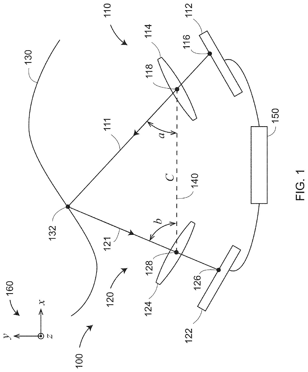
[0042]FIG. 1 is a schematic representation of a triangulation scanner 100 having a projector 110, a camera 120, and a processor 150. In an embodiment, the projector 110 includes a projection component 112 and a lens 114. The projection component 112 generates a pattern of light that includes an illuminated point 116 that is projected through a perspective center 118 of the lens 114 in a ray of light 111 that creates a spot of light 132 on an object 130. The camera 120 includes a photosensitive array 122 and a lens 124. A ray of light 121 emerges from the spot of light 132 and passes through a perspective center 128 of the lens 124 befor...


PUM


Abstract

A system includes a polarization target having two or more surfaces, a polarization camera that captures an image of the polarization target and records polarization of light that formed the image, and a processor that determines an orientation of the polarization target based at least in part on the captured image and the determined polarization.

Description

FIELD OF THE INVENTION[0001]The subject matter disclosed herein relates to registration of three-dimensional (3D) data points obtained using triangulation scanners.BACKGROUND[0002]A triangulation scanner, also referred to as a 3D imager, uses a triangulation method to measure the 3D coordinates of points on an object. The triangulation scanner usually includes a projector that projects onto a surface of the object either a pattern of light in a line or a pattern of light covering an area. At least one camera and the projector are coupled together in a fixed relationship. For example, the projector and the one or more cameras may be attached to a common frame. The light emitted from the projector is reflected off the object surface and detected by the camera(s). Since the camera(s) and projector are arranged in a fixed relationship, the distance to the object may be determined using trigonometric principles. Compared to coordinate measurement devices that use tactile probes, triangul...

Claims


Application Information

Patent Timeline
Patent Type & Authority Applications(United States)
IPC IPC(8): G01B11/25G01B21/04G02B26/10
CPCG02B26/10G01B21/04G01B11/2518G01B11/002G01B11/26G01B2210/52
Inventor WOLKE, MATTHIAS
Owner FARO TECH INC
Why Eureka
Try Eureka