Method for identifying the discrete instantaneous angular speed of an electromechanical system

a technology of instantaneous angular speed and electromechanical system, which is applied in the direction of dynamo-electric converter control, dynamo-electric gear control, dynamo-electric brake control, etc., can solve the problems of changes potentially indicating a problem in the machine, difficult installation of sensors, etc., and achieve the effect of minimizing residual errors

Active Publication Date: 2018-08-23
ABB (SCHWEIZ) AG
View PDF3 Cites 9 Cited by
  • Summary
  • Abstract
  • Description
  • Claims
  • Application Information

AI Technical Summary

Benefits of technology

[0012]In contrast to estimation techniques based on artificial intelligence which account for parametric variation during operation, the invention described here requires no training period in order to fit model parameters and no iterations are required to minimize residual errors. As the method is based on the use of measured data offline, the operations required are relatively straight forward, meaning that the approach is computationally efficient allowing it to be carried out on simple computing devices.

Problems solved by technology

These sensors can be difficult to install due to spatial considerations, inaccessibility or safety considerations.
Moreover, the rotor time constant estimated using the method may also be trended, with changes potentially indicating a problem in the machine.

Method used


Image

  • Method for identifying the discrete instantaneous angular speed of an electromechanical system
  • Method for identifying the discrete instantaneous angular speed of an electromechanical system
  • Method for identifying the discrete instantaneous angular speed of an electromechanical system

Examples


Embodiment Construction

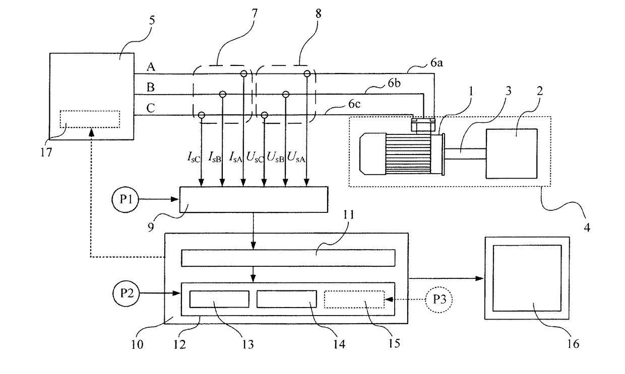
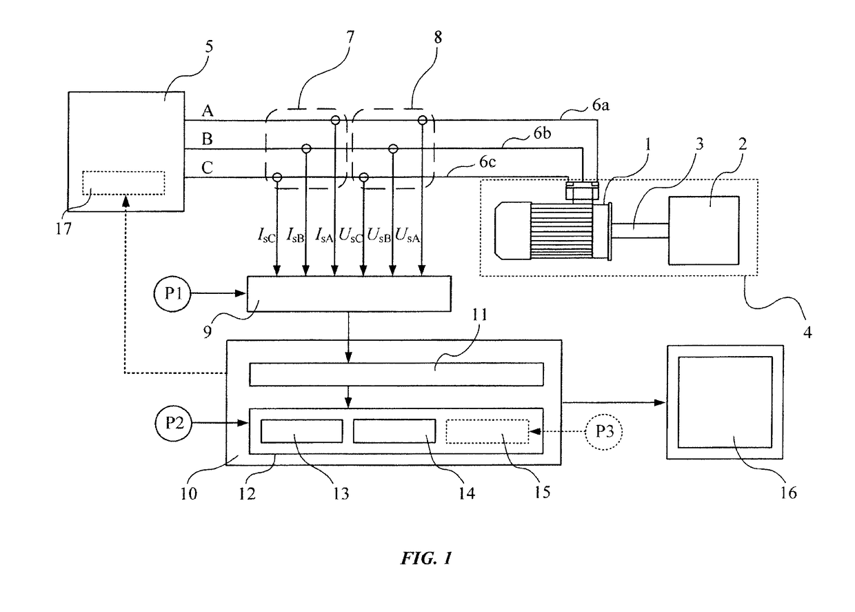
[0017]Referring to FIG. 1 there is depicted an example schematic of a physical realization of the invention. A three phase asynchronous electric motor 1 is used to drive a piece of rotating machinery 2 via a shaft coupling 3. The three phase asynchronous electric motor 1, the shaft coupling 3, and the rotating machinery 2, together comprise the electromechanical system 4. The electric power supply device 5 provides three-phase alternating current to the asynchronous electric motor 1 by way of power supply cables 6a, 6b and 6c. One or more outputs of current measuring devices 7, and / or voltage measuring devices 8 are connected with other inputs of the data acquisition unit 9. The data acquisition unit 9, which typically takes the form of an analog-to-digital converter is provided with a set of constant parameters P1, which characterize the process of converting the analog waveforms into the discrete signals, specifically the sampling rate Fs and the length of the signal subjected to ...


PUM


Abstract

A method for identifying the discrete instantaneous angular speed of electromechanical systems in which electrical rotating machinery is used and in which at least one electrical signal is measured during an operation of the electromechanical system. The method includes measuring analog stator current signals and analog stator voltage signals for at least one phase A, B, C, converting the measurements into a digital discrete form, transmitting the digital discrete signals to a computer device wherein data analysis is performed in a processor unit on the basis of a simplified mathematical model of the dynamics of the motor or generator. During the data analysis an average rotor time constant is calculated, an average supply frequency value is identified, an average angular speed is obtained, and an instantaneous phase difference between the discrete stator current signals and the discrete stator voltage signals is determined. The discrete instantaneous angular speed is identified by combining the average supply frequency value, the instantaneous phase difference between the discrete stator current signals and the discrete stator voltage signals, the average rotor time constant, and a number of pole pairs of the electric motor, given by the user. The result of combining the data is stored in a memory of the processor unit.

Description

[0001]The present invention is concerned with a method for identifying the discrete instantaneous angular speed of electromechanical systems in which electrical rotating machinery is used and in which at least one electrical signal is measured during an operation of the electromechanical system. The instantaneous angular speed may subsequently be used in further applications such as assessing the condition of the electromechanical system.BACKGROUND OF THE INVENTION[0002]Motor Current Signature Analysis (MCSA) represents a well-known and widely used approach for monitoring the health state of motors and generators. Traditional implementations of MCSA involve the analysis of the frequency spectrum of a measured motor phase current in order to ascertain certain fault modes such as air-gap eccentricity, broken rotor bars and bearing damage. Torsional oscillations can also modulate the phase currents drawn by both synchronous and asynchronous motors resulting in sidebands in the current ...

Claims


Application Information

Patent Timeline
Patent Type & Authority Applications(United States)
IPC IPC(8): H02P21/16H02P21/18H02P23/14
CPCH02P21/16H02P21/18H02P23/14H02P2207/01
Inventor OTTEWILL, JAMES
Owner ABB (SCHWEIZ) AG
Why Eureka
Try Eureka