Pneumatic Tire
- Summary
- Abstract
- Description
- Claims
- Application Information
AI Technical Summary
Benefits of technology
Problems solved by technology
Method used
Image

Examples
Embodiment Construction
[0022]Embodiments of the present technology are described in detail below based on the drawings. However, the technology is not limited to these embodiments. Constituents of the embodiments include elements that are essentially identical or that can be substituted or easily conceived by one skilled in the art. Furthermore, the modified examples described in the embodiments can be combined as desired within the scope apparent to one skilled in the art.
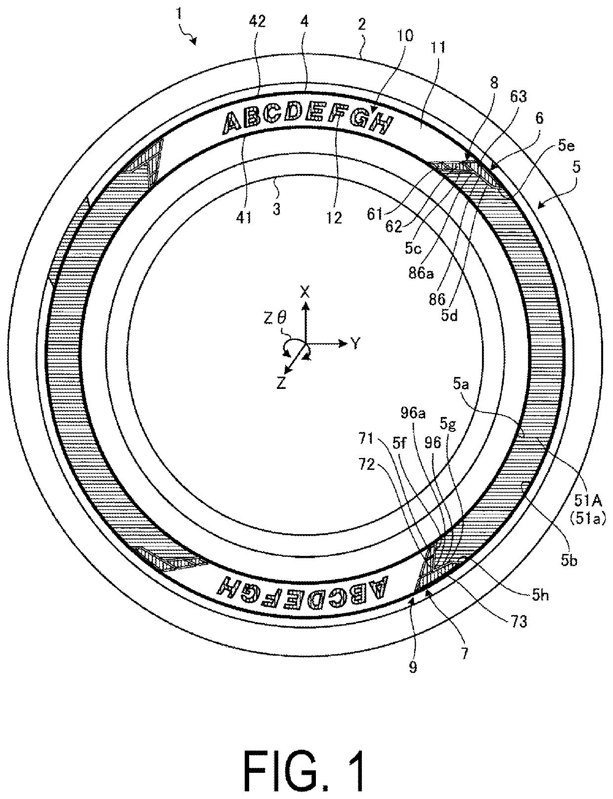
[0023]Hereinafter, a “tire lateral direction” refers to the direction parallel to a rotation axis (not illustrated) of the pneumatic tire 1, and an “outside in the tire lateral direction” refers to the direction away from a tire equatorial plane (tire equator line) in the tire lateral direction. A “tire circumferential direction” refers to the circumferential direction centered the rotation axis. In addition, a “tire radial direction” refers to the direction orthogonal to the rotation axis, an “inside in the tire radial direction” refer...
PUM
 Abstract
Description
Claims
Application Information
 - R&D
- Intellectual Property
- Life Sciences
- Materials
- Tech Scout
- Unparalleled Data Quality
- Higher Quality Content
- 60% Fewer Hallucinations
Browse by: Latest US Patents, China's latest patents, Technical Efficacy Thesaurus, Application Domain, Technology Topic, Popular Technical Reports.
© 2025 PatSnap. All rights reserved.Legal|Privacy policy|Modern Slavery Act Transparency Statement|Sitemap|About US| Contact US: help@patsnap.com