Cover apparatus for a motor vehicle body
a technology for motor vehicles and covers, applied in electric vehicle charging technology, charging stations, transportation and packaging, etc., can solve problems such as kinematic systems that are susceptible to dirt, and achieve the effects of preventing jamming, low friction loss, and facilitating displacemen
- Summary
- Abstract
- Description
- Claims
- Application Information
AI Technical Summary
Benefits of technology
Problems solved by technology
Method used
Image

Examples
first embodiment
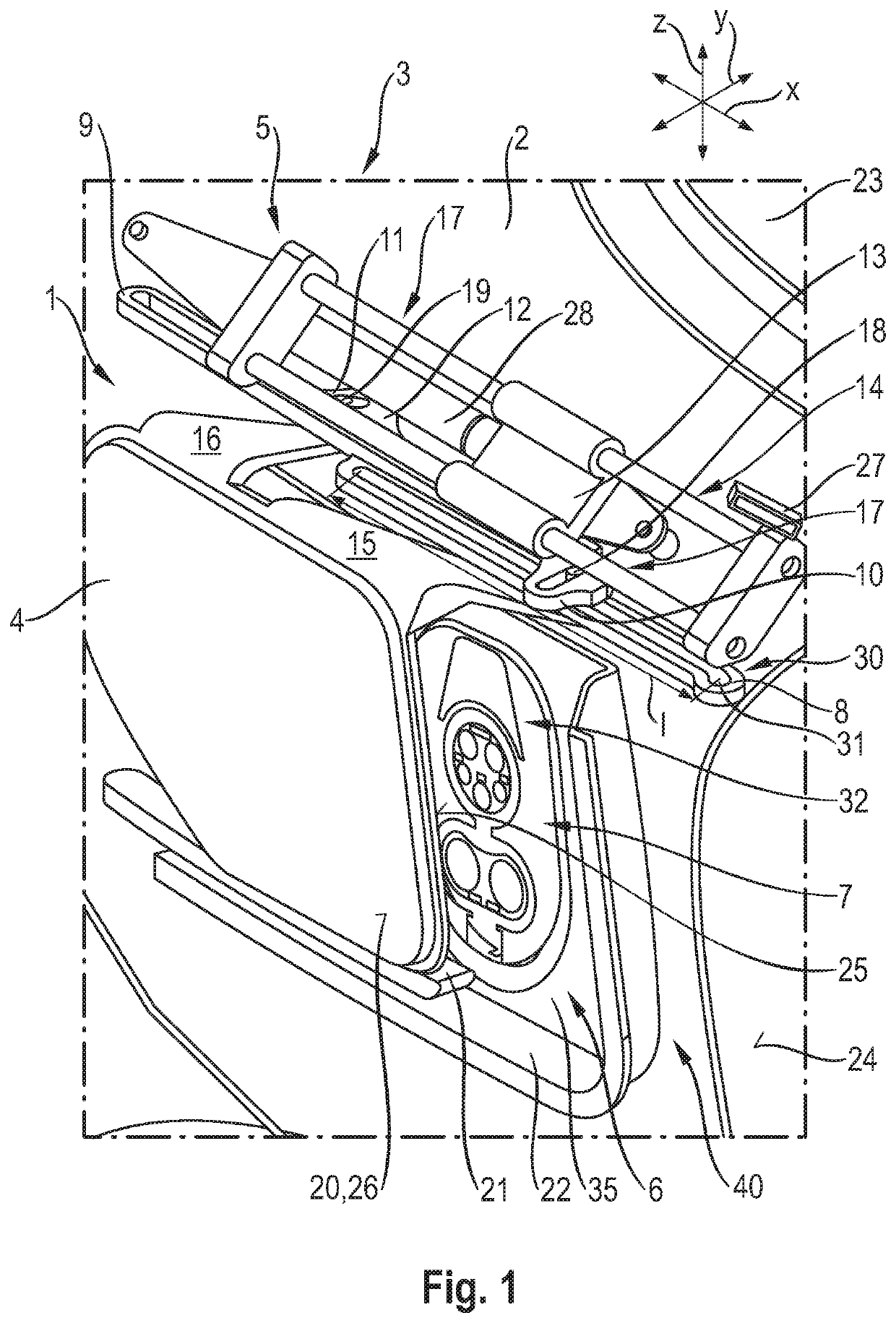
[0043]a cover apparatus 1 for a motor vehicle body 2 of a motor vehicle 3 is illustrated in FIG. 1. The cover apparatus 1 has a movable covering element 4 and a movement device 5, with the aid of which the covering element 4 can be moved relative to the motor vehicle body 2.
[0044]The covering element 4 is provided for covering a filling connector 7 of an energy supply element (not shown in greater detail). In this embodiment, the filling connector 7 is arranged on a receptacle element 35 of shell-like configuration that is configured so as to lie opposite the covering element 4. The receptacle element 35 is arranged in a vehicle body opening 40 of the motor vehicle body 2 and, in the installed state, is fixed with respect to the motor vehicle body 2.
[0045]The receptacle element 35 has a receptacle opening 6 that is configured for receiving the energy supply element and can be closed completely or partially by way of the covering element 4. Furthermore, the receptacle element 35 has ...
second embodiment
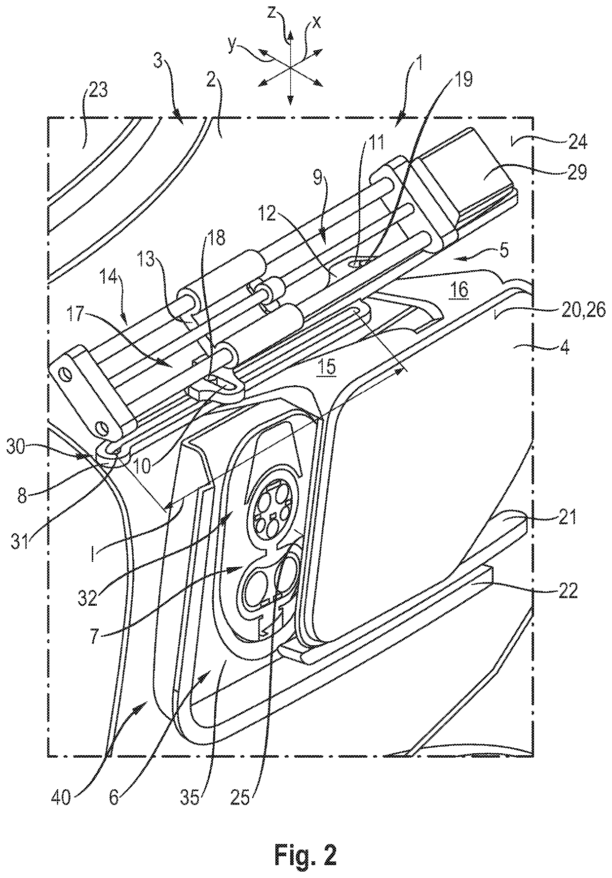
[0061]Instead of the prestressing element 28 and the latching element 27 configured in the form of a push-push element, the cover apparatus 1 is illustrated in FIGS. 2, 6 to 8 and 10 and uses an electric drive 29 which, by way of example, comprises a stepping motor as drive element. The movements of the covering element 4 are identical in the two exemplary embodiments, since the movement device 5 is also identical with the exception of the drive.
[0062]FIGS. 9 and 10 serve for improved explanation. FIG. 9 illustrates the motor vehicle body 2 with the closed receptacle opening 6, and FIG. 10 shows a transparent illustration of the motor vehicle body 2 to make the arrangement of the cover apparatus 1 visible in the case of a closed receptacle opening 6 using the example of the second embodiment. It can thus be shown that the movement device 5 and at least the holding arms 15, 16 are always positioned completely below the outer skin 24, and thus between the outer skin 24 and the vehicle...
third embodiment
[0068]The prestressing element 28 (configured in the form of a spiral spring) of the third embodiment is supported on a guide rod 34 that extends in the direction of the vehicle body longitudinal axis x, as can be gathered from FIG. 12.
[0069]Above the filling gauge 32 in the direction of the motor vehicle vertical axis z, the receptacle element 35 has an illumination element 33 in the form of an LED light strip for improved visibility of the filling gauge 32. The illumination element 33 is actuated with the aid of a control element 42 in the form of a switch that is actuated when the closed position of the covering element 4 is reached or left.
[0070]The element bar 21 of the covering element 4 of the third embodiment further has a third guide element 43 in the form of a cylindrical pin that is configured to engage into the supporting rail 22.
[0071]FIGS. 13 and 14 illustrate the cover apparatus 1 according to a fourth embodiment where an electric drive 29 is provided in contrast to t...
PUM
 Abstract
Description
Claims
Application Information
 - R&D Engineer
- R&D Manager
- IP Professional
- Industry Leading Data Capabilities
- Powerful AI technology
- Patent DNA Extraction
Browse by: Latest US Patents, China's latest patents, Technical Efficacy Thesaurus, Application Domain, Technology Topic.
© 2024 PatSnap. All rights reserved.Legal|Privacy policy|Modern Slavery Act Transparency Statement|Sitemap