Valve

a valve and valve body technology, applied in the field of valves, can solve the problems of limited adaptation effort, and achieve the effects of reducing friction, and reducing the risk of valve damag

Inactive Publication Date: 2020-10-15
VITESCO TECH GERMANY GMBH
View PDF0 Cites 0 Cited by
  • Summary
  • Abstract
  • Description
  • Claims
  • Application Information

AI Technical Summary

Benefits of technology

[0004]An object of the invention is therefore to provide a valve that makes possible simple sealing of the piston against the housing. The valve should furthermore be inexpensive.
[0005]The object may be achieved in accordance with one aspect of the invention, by a seal as a disk having a radially inner sealing surface, which is clamped at the radially outer edge in the housing. The cross section of such a seal is significantly simpler and thus less expensive than conventional seals. It has surprisingly been found that reliable sealing of the piston can be accomplished, despite the simple cross-sectional geometry, if the seal is clamped in place. Here, the disk shape offers a suitable geometry, and therefore clamping can likewise be performed with little effort.

Problems solved by technology

The effort involved in adaptation is therefore limited.

Method used


Image

  • Valve
  • Valve

Examples


Embodiment Construction

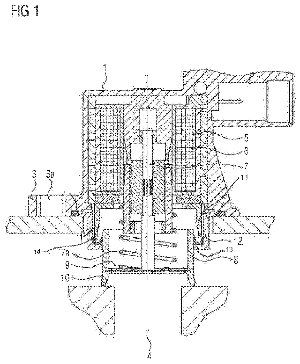
[0017]FIG. 1 shows the valve, which comprises a housing 1. The housing 1 furthermore has an integrally formed flange 3, via which the housing 1 is flanged-mounted on a turbocharger (not illustrated) in the region of a bypass line 4. In the housing 1, there is arranged a solenoid 5 with a coil 6 and a metal pin 7. The metal pin 7 is connected to a cup-shaped piston 8 which has a seal 10 at the periphery of its base 9. Here, a spring 7a pushes the piston 8 in the direction of the valve seat.

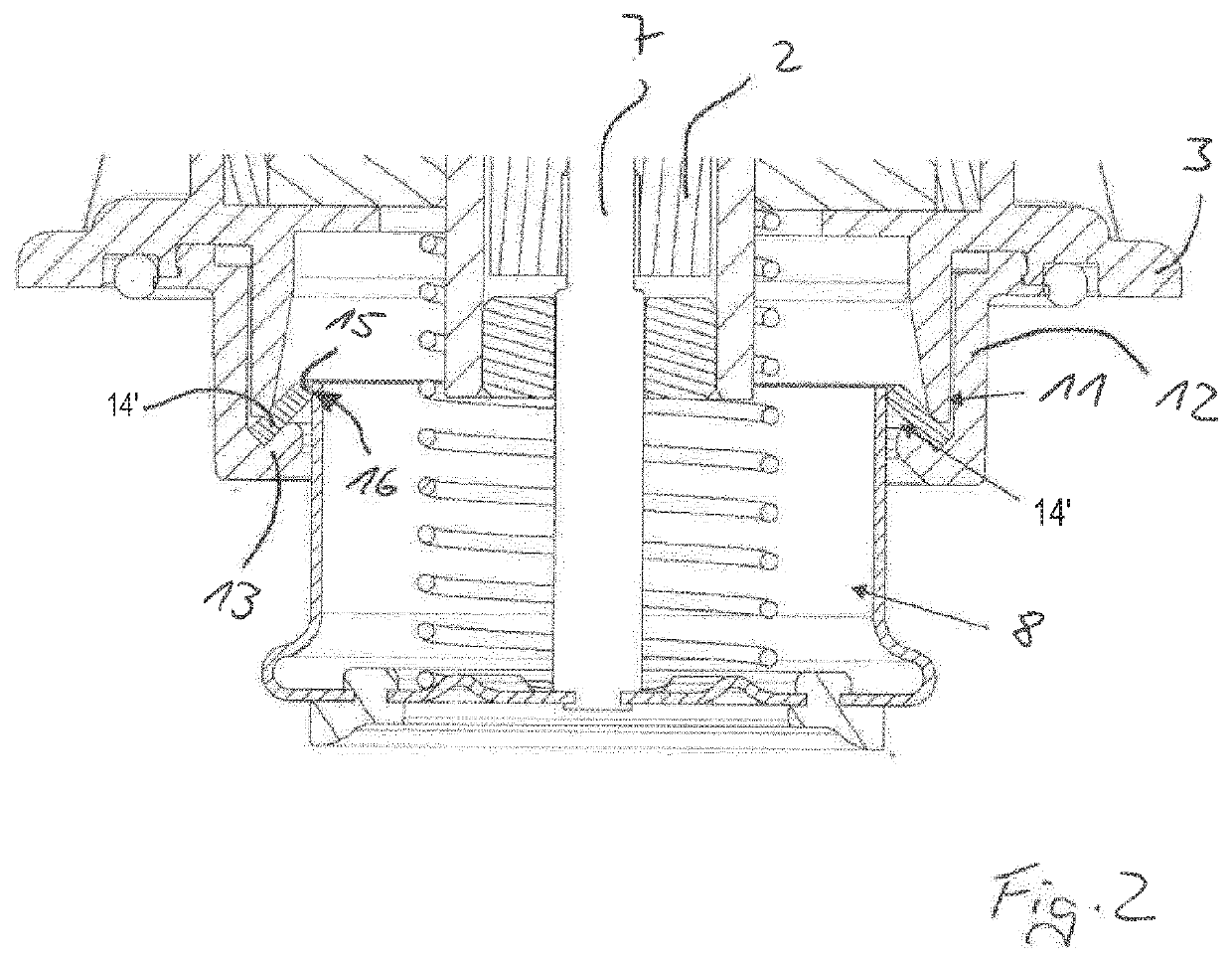
[0018]The housing 1 furthermore has a cylindrical section 11 which extends in the direction of the piston 8. A cylinder bushing 12 connected to the housing 1 surrounds the cylindrical section 11. The cylinder bushing 12 has a radially inwardly directed collar 13, on which a V-shaped seal 14 rests. The end of the cylindrical section 11 holds the seal 14 in position. The inner limb of the seal 14 seals the piston against the housing. If the solenoid 5 is electrically energized, a magnetic force acts ...


PUM


Abstract

A valve includes: a housing; a solenoid arranged in the housing; a pin movable by the solenoid; a cup-shaped piston connected to the pin; and a seal arranged in the housing and configured to seal the piston against the housing. The seal is a disk having a radially inner sealing surface clamped at a radially outer edge in the housing.

Description

CROSS REFERENCE TO RELATED APPLICATIONS[0001]This is a U.S. national stage of International application No. PCT / EP2018 / 085828, filed on Dec. 19, 2018, which claims priority to German Application No. 10 2017 223 583.7, filed Dec. 21, 2017, the content of each of which is incorporated herein by reference.BACKGROUND OF THE INVENTION1. Field of the Invention[0002]The invention relates to a valve having a housing, a solenoid arranged in the housing, a pin movable by the solenoid, a cup-shaped piston, which is connected to the pin, and a seal, which is arranged in the housing and seals the piston against the housing.2. Related Art[0003]Such valves are used, inter alia, as a diverter valve on the turbocharger in motor vehicles to open up a bypass to the suction side in overrun operation, and are thus known. In order to prevent excessive deceleration of the turbocharger, but also to ensure a fast start-up, rapid opening and closing of the valve are essential prerequisites. In particular dur...

Claims


Application Information

Patent Timeline
Patent Type & Authority Applications(United States)
IPC IPC(8): F16K1/46F16K1/36F16K31/06F16J15/10
CPCF16K1/46F16J15/106F16K31/0655F02B37/16F16K1/36F16J15/061F16J15/062F16J15/0887Y02T10/12
Inventor BONANNO, ROSARIO
Owner VITESCO TECH GERMANY GMBH
Why Eureka
Try Eureka