
Battery module

Active Publication Date: 2020-10-15
LG ENERGY SOLUTION LTD
View PDF20 Cites 0 Cited by
  • Summary
  • Abstract
  • Description
  • Claims
  • Application Information

AI Technical Summary

Benefits of technology

The patent describes a battery module that can cool down high temperatures and support its battery cell at low temperatures to prevent swelling. This results in a more efficient and safe battery that can be used for longer periods of time.

Problems solved by technology

Meanwhile, a battery cell is swollen by a swelling phenomenon caused by decomposition or side reaction of the electrolyte when the battery cell is stored at high temperatures for a long time, or an abnormality, such as overcharge, overdischarge, or an internal short circuit due to a failure in a charger or a front control circuit, occurs.
Such a swelling phenomenon increases the volume of a pouch exterior material, and weakens the adhesion of a sealing area of the pouch exterior material to leak the electrolyte through the sealing area of the pouch exterior material or cause acceleration of the side reaction of the electrolyte to place the inside of the pouch exterior material in a high-temperature and high-pressure environment, thereby igniting or exploding the battery cell.
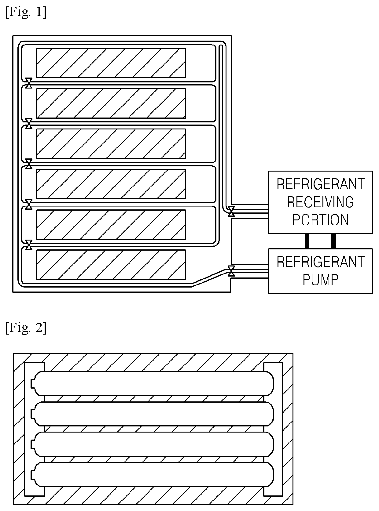
The method as described above has an advantage of quickly reducing the temperature of the battery cells by directly lowering the temperature of the battery cells through the refrigerant, but cannot deal with an issue that a swelling phenomenon occurs at low temperatures.
However, the structure as described above has an issue that, since the large surfaces of the battery cells are not exposed externally, it is difficult to form a cooling passage for cooling the respective battery cells.

Method used


Image

  • Battery module
  • Battery module
  • Battery module

Examples


embodiment 1

[0044]Hereinafter, a battery module in accordance with an embodiment of the present disclosure will be described.

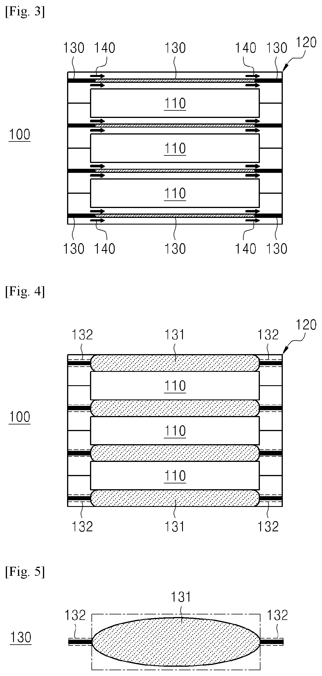
[0045]The battery module, according to the embodiment of the present disclosure, is formed as a structure in which the shape of a filling portion, which is disposed between battery cells to curb or reduce a swelling phenomenon that is accelerated at high temperatures, is transformed itself according to temperatures, so as to be able to protect the battery cells without an additional control, thereby being capable of being driven safely and efficiently.

[0046]FIG. 3 is a structural view of a lateral surface of a battery module that includes filling portions with a volume reduced in a high-temperature state in accordance with an exemplary embodiment.

[0047]FIG. 4 is a structural view of the lateral surface of the battery module that includes the filling portions with a volume increased in a low-temperature state in accordance with an exemplary embodiment.

[0048]Referring to FI...

embodiment 2

[0086]Hereinafter, a battery module in accordance with another embodiment of the present disclosure will be described.

[0087]The battery module, in accordance with the other embodiment of the present disclosure, is formed as a structure in which a battery cell is supported according to a swelling probability that increases over a driving time of the battery module to form a cooling passage instead of an inefficient swelling suppression structure at the beginning of battery module driving, thereby being capable of being driven safely and efficiently.

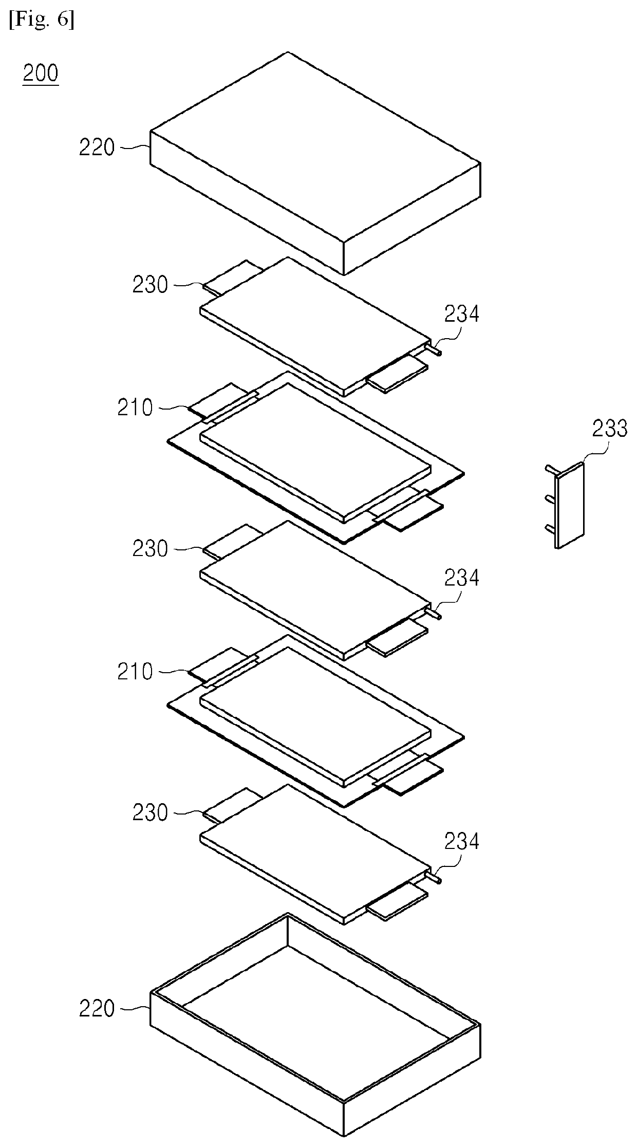
[0088]FIG. 6 is a perspective view of a battery module in accordance with another exemplary embodiment.

[0089]Referring to FIG. 6, a battery module 200 in accordance with another embodiment includes a plurality of battery cells 210, a module case 220 having the plurality of battery cells received therein, and filling portions 230 provided between the module case 220 and the battery cells 210 and between the plurality of battery cells 210.

[0...


PUM


Abstract

The present disclosure relates to a battery module that has a filling portion transformed into a structure in which a battery cell is supported such that swelling pressure generated when swelling occurs is offset without an additional control, or a structure in which the battery cell is efficiently cooled.

Description

TECHNICAL FIELD[0001]The present disclosure relates to a battery module, and more particularly, to a battery module that has a filling portion transformed into a structure in which a battery cell is supported such that swelling pressure generated when swelling occurs according to temperatures is offset without an additional control, or a structure in which the battery cell is efficiently cooled.BACKGROUND ART[0002]A rapid increase in use of fossil fuel increases a demand for use of alternative or clean energy. As part of the demand, the most actively studied fields is a power generation and storage field using electrochemistry.[0003]At present, a typical example of an electrochemical device using such electrochemical energy is a battery, and the application area tends to be gradually increasing.[0004]In recent days, as the technology development and demand for portable devices, such as a portable computer, a mobile phone, and a camera, has increased, the demand for a battery as an e...

Claims


Application Information

Patent Timeline
IPC IPC(8): H01M10/6556H01M2/10H01M10/613H01M10/647H01M50/204H01M50/242
CPCH01M2/1077H01M10/613H01M10/6556H01M10/647H01M10/655Y02E60/10H01M10/0481H01M10/615H01M10/6555H01M10/6563H01M10/6557H01M50/24Y02P70/50H01M50/204H01M50/242H01M10/659H01M50/258
Inventor KWON, DONG KEUNSONG, YEE GAHNG
Owner LG ENERGY SOLUTION LTD
Learn More