Printing apparatus, control method thereof and storage medium

Active Publication Date: 2020-10-29
CANON KK
View PDF0 Cites 0 Cited by
  • Summary
  • Abstract
  • Description
  • Claims
  • Application Information

AI Technical Summary

Benefits of technology

[0007]Consequently, in view of the above-described problem, an object of one embodiment of the present disclosure is to optimize the time necessary f

Problems solved by technology

However, Japanese Patent Laid-Open No. 2015-44357 does not take into consideration the state of the ink supply path after ink is pulled out and in a case where the

Method used


Image

  • Printing apparatus, control method thereof and storage medium
  • Printing apparatus, control method thereof and storage medium
  • Printing apparatus, control method thereof and storage medium

Examples


Example

[0078]In the first embodiment, the number of times of ink suction is changed in accordance with the elapsed time from the ink pulling out in the ink discharge sequence, which is performed before the secondary transport, to the start of the ink filling performed at the time of installation after the secondary transport. In contrast to this, in the present embodiment, the number of times of suction is changed depending on whether or not the ink discharge sequence is performed before the ink filling.

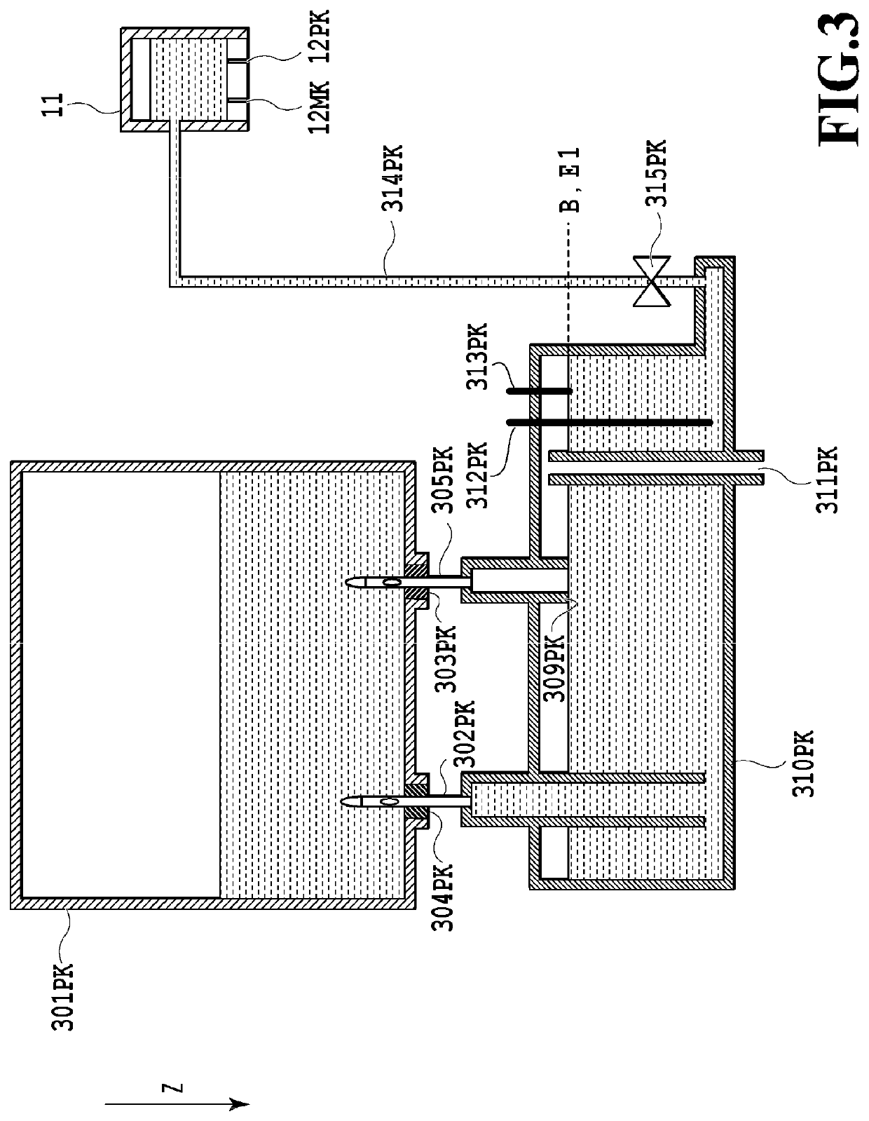
[0079]As described previously, in a case where the ink discharge sequence is performed, the ink film occurs within the ink supply tube 314 and the flow path in the print head 11 and the ink film serves as a resistance at the time of the ink filling afterward. However, the ink discharge sequence such as this is not necessarily performed at all times for the purpose of the ink pulling out. In the present embodiment, attention is focused on a case where the ink discharge sequence is not perfor...

Example

Third Embodiment

[0092]In the first embodiment, the number of times of suction is changed in accordance with the elapsed time from the ink pulling out in the ink discharge sequence. In contrast to this, in the present embodiment, the number of times of suction is changed in accordance with the temperature at the time of execution of the ink discharge sequence.

[0093]As described previously, in a case where the ink discharge sequence is performed, the ink film occurs within the ink supply tube 314 and the flow path in the print head 11 and the ink film serves as a resistance at the time of the ink filling, but the higher the temperature, the more unlikely the ink film occurs and the more likely the ink film disappears. Consequently, the present embodiment focuses attention on that the degree of occurrence of the ink film is different and the resistance in the tube and the flow path within the head is different in accordance with the ink temperature.

[0094]In the following, the ink disch...


PUM


Abstract

The object of the present disclosure is to optimize the time necessary for filling and the ink consumption. One embodiment of the present disclosure is a printing apparatus having: a storage unit; a print head having an ejection port from which ink supplied from the storage unit is ejected; an ink supply path that connects the storage unit and the print head; a suction unit configured to perform suction at the ejection port; and a supply control unit configured to supply ink stored in the storage unit to the ink supply path and the print head by performing suction at the ejection port by the suction unit, and the printing apparatus has an acquisition unit configured to acquire information relating to ink discharge from the ink supply path and the supply control unit determines the number of times of suction by the suction unit based on the information.

Description

BACKGROUND OF THE INVENTIONField of the Invention[0001]The present application relates to a printing apparatus, a control method thereof, and a storage medium.Description of the Related Art[0002]Conventionally, the ink jet printing technique has been widely researched and developed in view of advantages, such as that printers can be manufactured at comparatively low costs, and an ink jet printing apparatus has prevailed widely as consumer equipment, such as a printer and a multifunction peripheral.[0003]Further, in recent years, the demand to increase the amount of ink that is stored within the ink jet printing apparatus is increasing. Because of this, a printer having a sub tank for storing ink, in addition to an ink tank, has been proposed. By providing a sub tank, it is made possible to continue printing without interruption even while a user is exchanging an ink tank with another. Among the ink jet printing apparatuses, many of them adopt a method of keeping the pressure within ...

Claims


Application Information

Patent Timeline
IPC IPC(8): B41J2/165
CPCB41J2/16523B41J2/16508B41J2/1652B41J2/16532
Inventor NARUMI, KAZUKIKATO, MASATAKADANZUKA, TOSHIMITSUFUJIMOTO, YASUNORIGENTA, SHINYAMAMURO, TOMOKIKANGO, HIROTOSATO, KAZUHIKOSUZUKI
Owner CANON KK
Why Eureka
Try Eureka