
Thixotropic Non-cementitious Thermal Grout and HDD or Trough Product Line Methods of Application

a non-cementitious, thermal grout technology, applied in the direction of drilling composition, drilling apparatus and processes, electric cable installations, etc., can solve the problems of high or higher temperature, high or high temperature, and time sensitive processes

Active Publication Date: 2020-11-05
QUANTA ASSOC
View PDF0 Cites 1 Cited by
  • Summary
  • Abstract
  • Description
  • Claims
  • Application Information

AI Technical Summary

Benefits of technology

The patent describes a thixotropic, non-cementitious thermal grout that can be used in horizontal directional drilling and trenching applications. The grout is designed to fill the spaces between cables / conduits / ducts / product lines and help with installation. The grout can be used to create a stable barrier to prevent leaks and corrosion, and to protect the lines from damage during installation. The patent also describes methods for using the grout and product lines in horizontal directional drilling and trenching applications. The technical effects of the patent are the creation of a more stable and reliable barrier for the installation of cables / conduits / ducts / product lines, reducing the risk of leaks, corrosion, and damage during installation.

Problems solved by technology

The process is time sensitive because the concrete will set.
The standard or traditional cementitious grouts, e.g. those comprising Portland cement, do not flow well, have high or higher temperatures due to heat of hydration which may deform, e.g., a duct or other apparatus, and become solid after (and maybe even during) their installation.
Further, these traditional cementitious grouts irreversibly “set” after a period of time, and may put impractical or impossible time constraints on installation projects.
Moreover, the voids and air pockets of the traditional cementitious grouts are undesirable and detrimental to cables.

Method used


Image

  • Thixotropic Non-cementitious Thermal Grout and HDD or Trough Product Line Methods of Application
  • Thixotropic Non-cementitious Thermal Grout and HDD or Trough Product Line Methods of Application
  • Thixotropic Non-cementitious Thermal Grout and HDD or Trough Product Line Methods of Application

Examples


working example

[0058

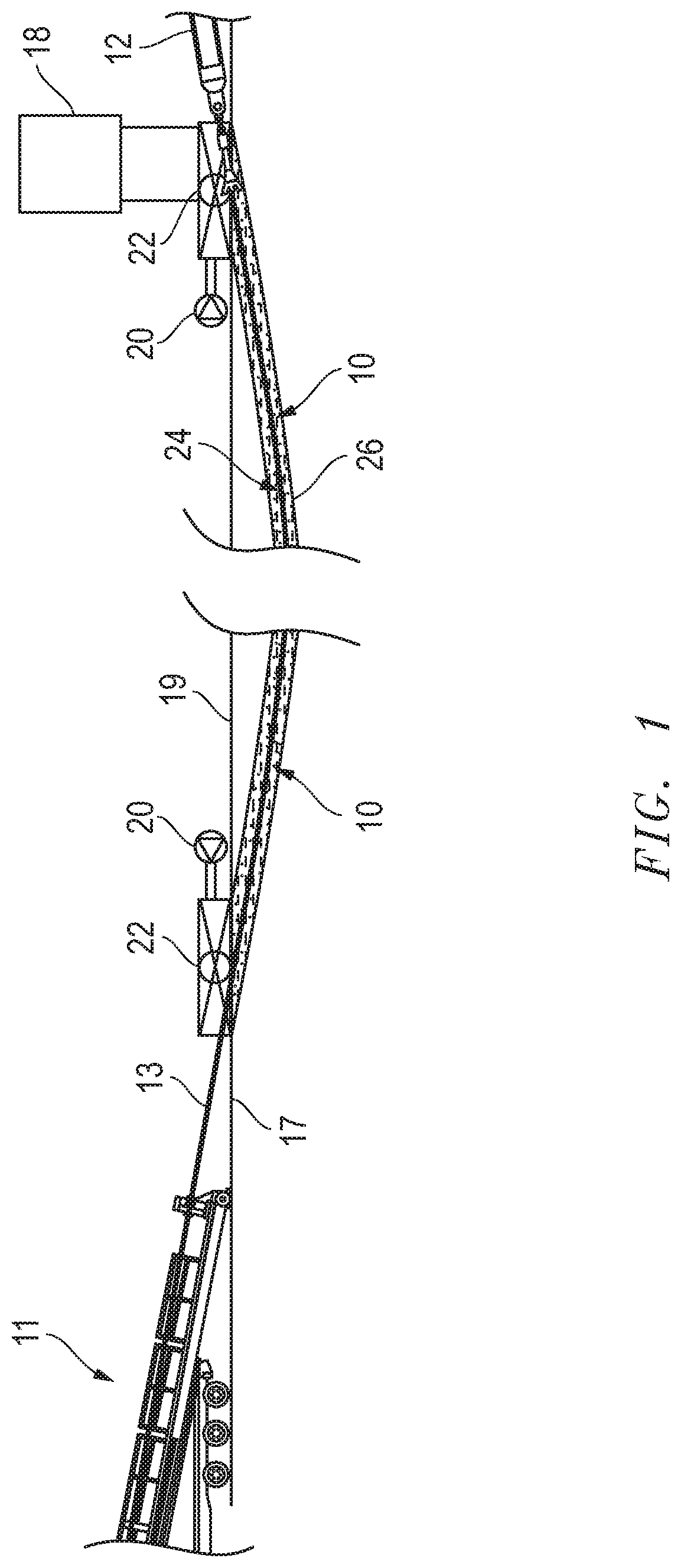
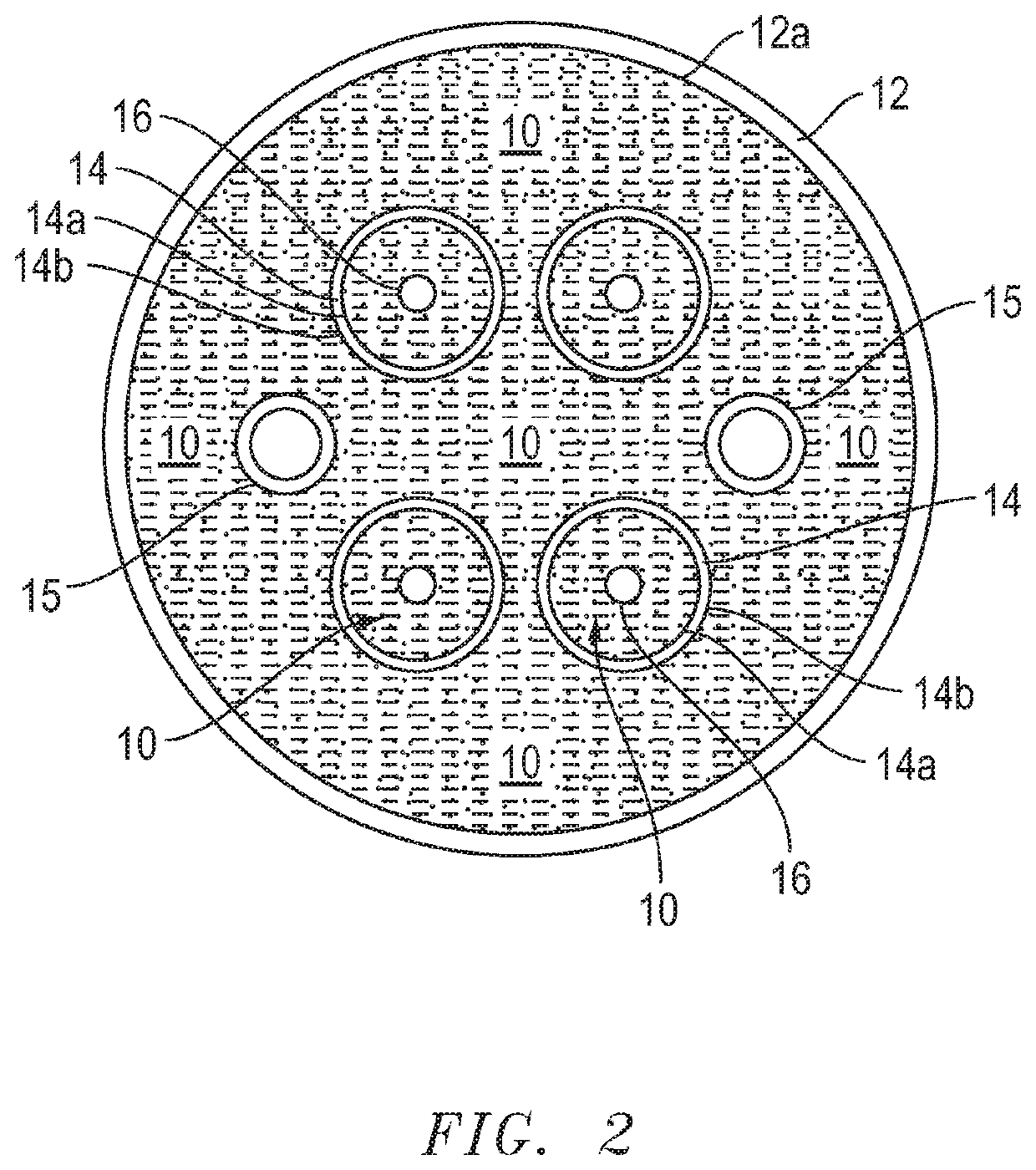
[0059]In one working example referring to FIGS. 1 & 2 a ball valve or valves 22 may be connected to a conduit 14 or casing 12 to be filled with the thixotropic non-cementitious thermal grout 10. A frac tank 18 may be connected proximate the entrance and / or exit to supply the thixotropic non-cementitious thermal grout 10. Vacuum pump(s) 20 are also connected to the conduit 14 or casing 12 to be filled. Vacuum pump(s) 20 are turned on to pull, by way of example only, a vacuum pressure of −10 psi atmospheric pressure. Specific ball valve(s) 22 (or ball valve(s) in combination with rotating devices) may then be opened to allow the thixotropic non-cementitious thermal grout 10 to flow gravitationally (the grout 10 flows freely) into the conduit 14 or casing 12 utilizing the volume stored in the frac tank 18 until the conduit 14 or casing 12 is filled completely or as desired. Some of the vacuum pressure may be lost during this step or as the conduit 14 or casing 12 is filled. If nee...


PUM

PropertyMeasurementUnit
densityaaaaaaaaaa
specific gravityaaaaaaaaaa
pHaaaaaaaaaa

Abstract

The disclosure relates to embodiments of a thixotropic, non-cementitious, thermal grout and applications or methods of use of the grout related to horizontal directional drilling, trenchless technology, trenching, and installation of pipe, conduits, ducts, utility lines, and other product lines which may, e.g., be in trenches, underground, or under obstacles, such as a body of water or roadways.

Description

TECHNICAL FIELD[0001]The disclosure relates to the field of horizontal directional drilling, trenchless technology, trenches, and grouts for installation of pipe, conduits, ducts, utility lines, and other product lines underground or under obstacles, such as a body of water or roadways.BACKGROUND[0002]Installation of electrical lines or underground cables has traditionally involved pumping a concrete mix into the annular space around electrical lines or underground cables. The process is time sensitive because the concrete will set. For example, such concrete mixtures may set in about twelve (12) hours or less. Additionally, the concrete has air pockets or voids such that fill rates or percentages may typically be 50-60%, or even as low as 40%.[0003]The standard or traditional cementitious grouts, e.g. those comprising Portland cement, do not flow well, have high or higher temperatures due to heat of hydration which may deform, e.g., a duct or other apparatus, and become solid after...

Claims


Application Information

Patent Timeline
Patent Type & Authority Applications(United States)
IPC IPC(8): C04B28/00C04B22/00C04B14/10
CPCC04B28/00C04B2111/0012C04B2111/70C04B2111/1037C04B14/104C04B22/002H02G3/04C04B2111/00112C04B2201/20C04B2201/30C04B30/00H02G1/081H02G3/086C04B2111/763C04B14/06C04B20/0008C04B20/0016C04B22/10C09K8/14
Inventor HALDERMAN, RONALD G.GUERRA, PABLO ESTEBAN
Owner QUANTA ASSOC
Learn More