
Communication unit and vehicle

Pending Publication Date: 2020-11-12
YAMAHA MOTOR POWER PROD KK
View PDF0 Cites 0 Cited by
  • Summary
  • Abstract
  • Description
  • Claims
  • Application Information

AI Technical Summary

Benefits of technology

The invention provides communication units that can be located close to the ground without needing to be completely sealed. These units are easy and cheap to manufacture and can be used in vehicles. The technical effect is that these communication units are less affected by water and can be more easily used in various situations.

Problems solved by technology

Further, an adjustment work of the circuit block cannot be performed after sealing.
Further, it is difficult and costly to manufacture a communication unit having a completely sealed structure.

Method used


Image

  • Communication unit and vehicle
  • Communication unit and vehicle
  • Communication unit and vehicle

Examples


Embodiment Construction

[0043]Communication units and vehicles including the communication units according to preferred embodiments of the present invention will be described below.

(1) Configuration of Communication Unit

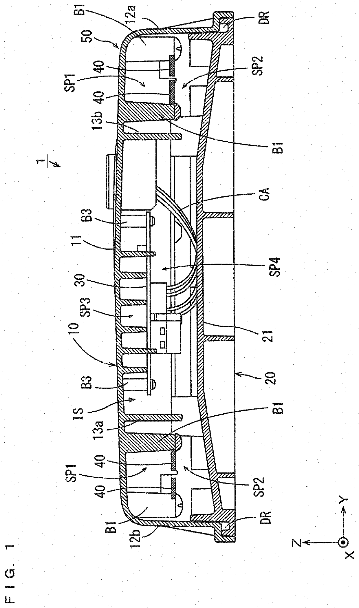
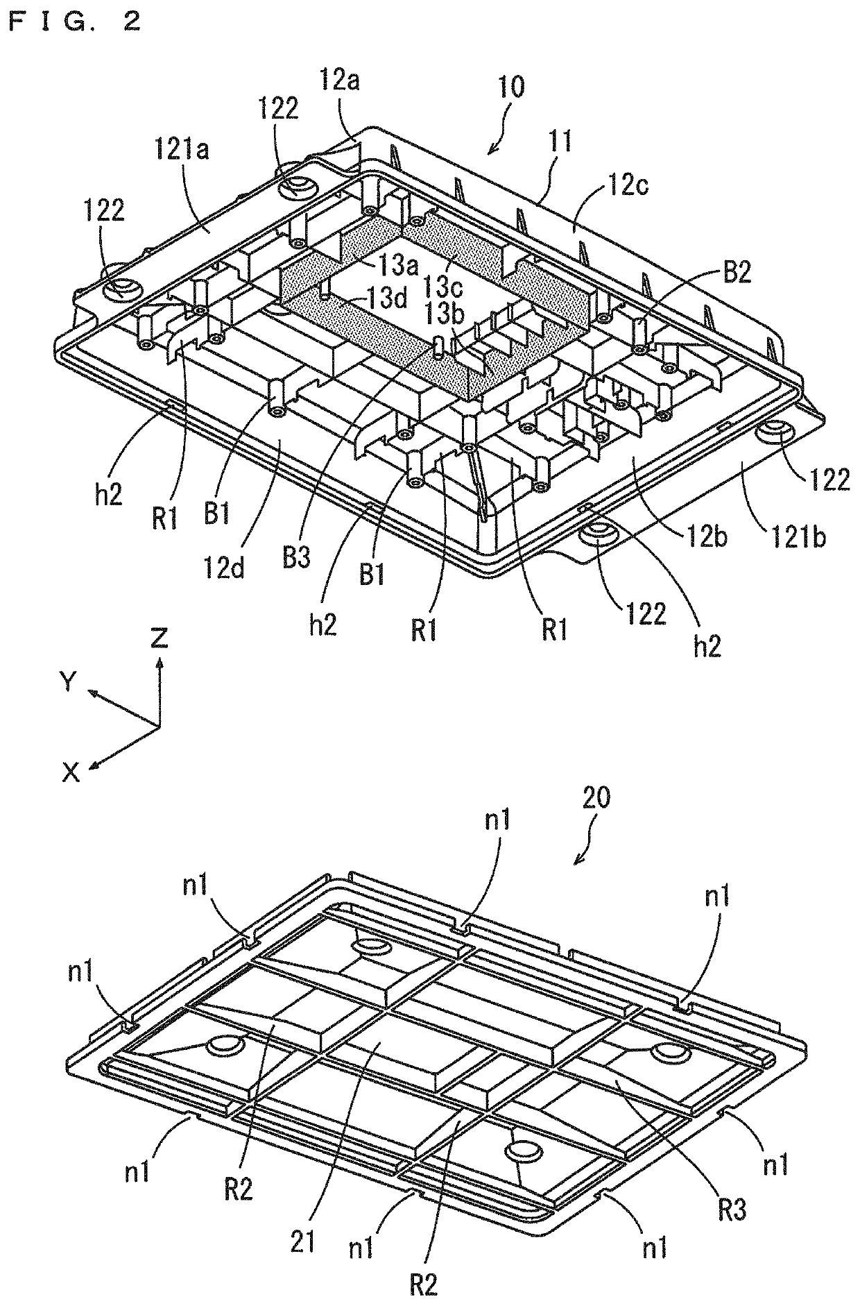
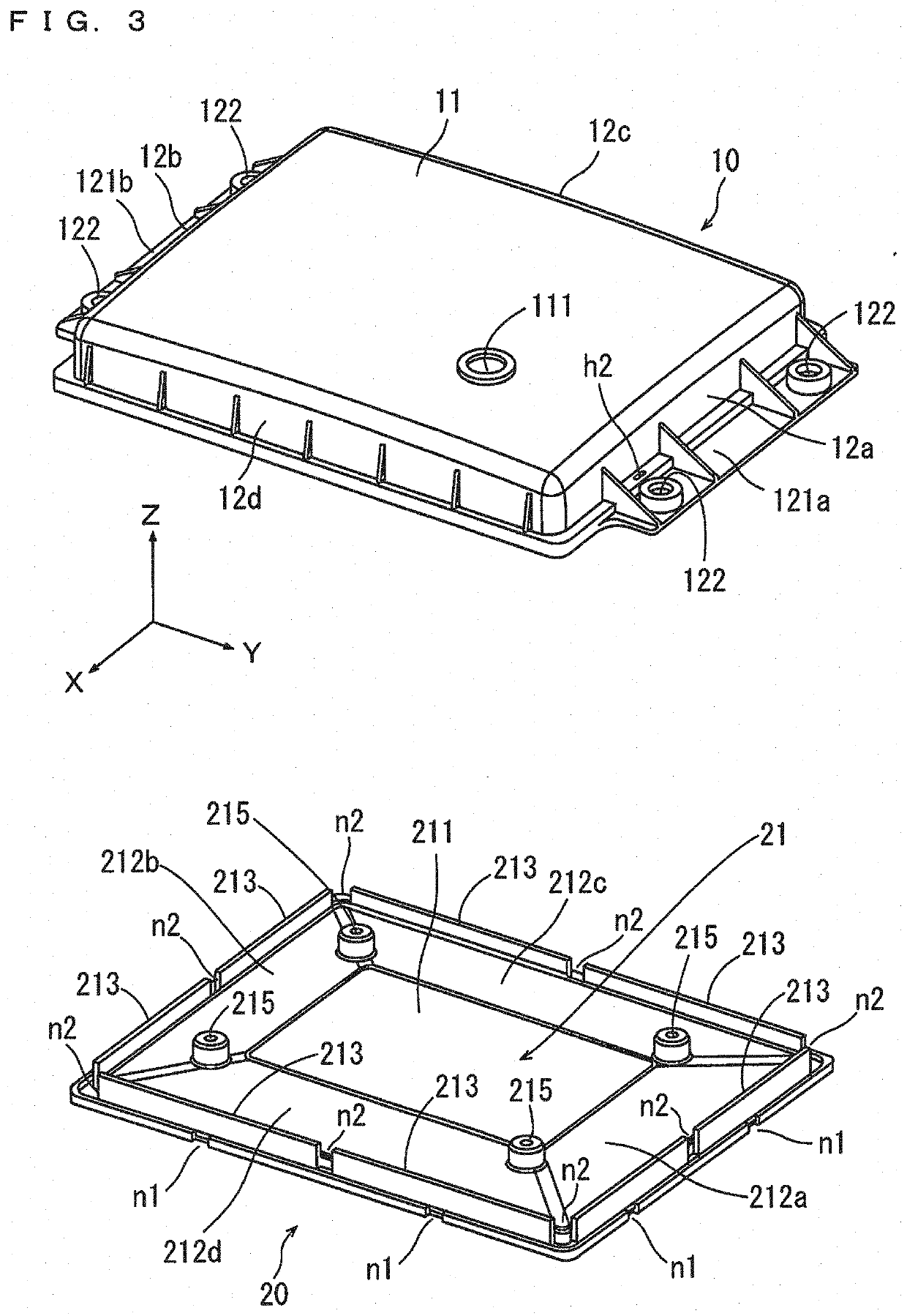
[0044]FIG. 1 is a cross-sectional view of the communication unit according to a preferred embodiment of the present invention. FIG. 2 is an exploded perspective view of the communication unit in a case where a housing of the communication unit of FIG. 1 is viewed from obliquely below. FIG. 3 is an exploded perspective view of the communication unit in a case where the casing of the communication unit of FIG. 1 is viewed from obliquely above. FIGS. 1 to 3 and the subsequent figures are accompanied by arrows that indicate X, Y, and Z directions orthogonal to one another for the clarity of a positional relationship. The X and Y directions are orthogonal to each other in a horizontal plane, and the Z direction corresponds to a vertical direction.

[0045]As shown in FIG. 1, the communication unit ...


PUM


Abstract

A communication unit includes a circuit board on which a communication circuit is provided, an antenna connected to the circuit board, and a housing storing the circuit board and the antenna. The housing includes an upper plate, a lower plate, and an outer wall. The upper plate is located above the lower plate. An inner space is defined by the upper plate, the lower plate, and the outer wall. In the inner space, an inner wall surrounds the entire periphery of the circuit board in a plan view and projects from a lower surface of the upper plate to a position farther downward than the circuit board in a side view.

Description

BACKGROUND OF THE INVENTION1. Field of the Invention[0001]The present invention relates to a communication unit and a vehicle including the communication unit.2. Description of the Related Art[0002]For example, a communication unit that communicates with a predetermined fixed point on a traveling path is provided in a vehicle such as a golf cart that moves along an electromagnetic induction line buried in the ground. Since the communication unit is provided in a lower part of the vehicle, so that it is necessary to reduce the influence of water, mud or the like to be received from the ground.[0003]In JP 2007-300198 A, a sealing structure of an electric appliance is described. In the sealing structure of JP 2007-300198 A, the inside of a casing is partitioned into a first storage space and a second storage space by a partition plate. A circuit block is stored in the first storage space, and an antenna block is stored in the second storage space. The circuit block is sealed with a sea...

Claims


Application Information

Patent Timeline
IPC IPC(8): B60R11/02H05K5/02B60R16/023H01Q1/20H04B1/3822
CPCH01Q1/20B60R16/023H04B1/3822B60R11/02H05K5/0239H04B1/38H01Q1/3283B60R16/02H01Q1/12H01Q1/32H04B2001/3894H05K5/03
Inventor OMURA, YUICHI
Owner YAMAHA MOTOR POWER PROD KK
Learn More