Golf club head
- Summary
- Abstract
- Description
- Claims
- Application Information
AI Technical Summary
Benefits of technology
Problems solved by technology
Method used
Image
Examples
first embodiment
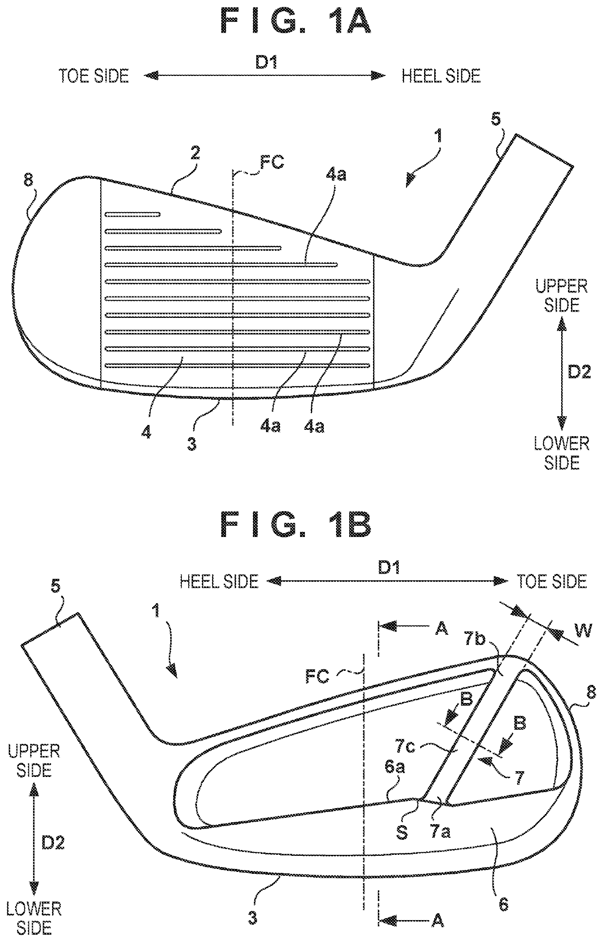
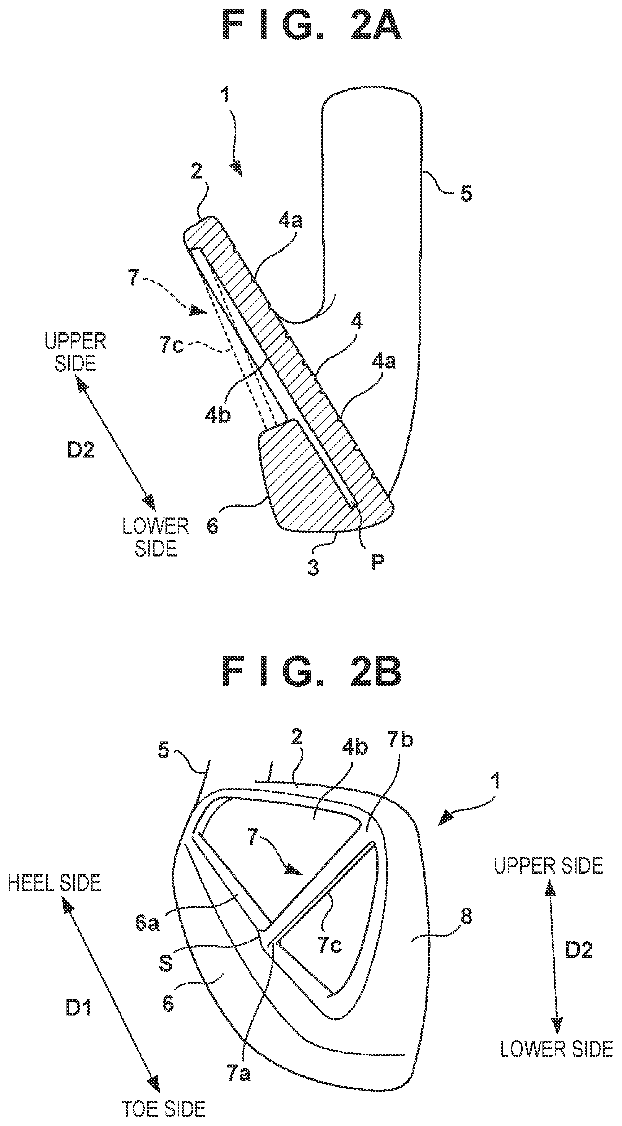
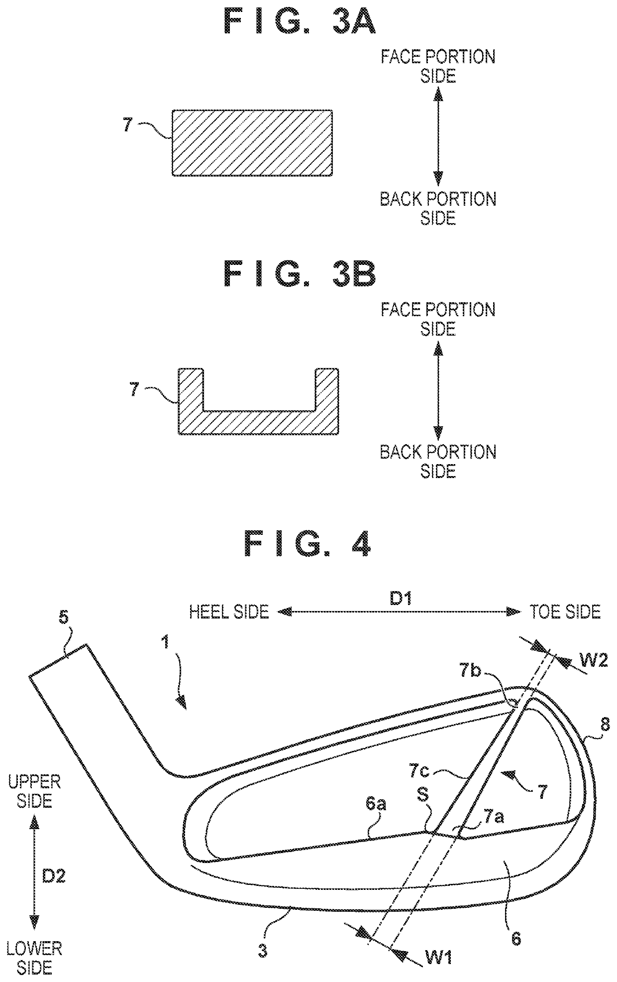
[0018]With reference to FIGS. 1A to 3A, a golf club head 1 according to an embodiment of the present invention will be described. FIG. 1A is a front view of the golf club head 1, and FIG. 1B is a back view thereof. FIG. 2A is a sectional view taken along a line A-A in FIG. 1B, FIG. 2B is a perspective view of the golf club head 1 viewed from a toe side, and FIG. 3A is a sectional view taken along a line B-B in FIG. 1B. In the drawings, an arrow D1 indicates a toe-heel direction, and an arrow D2 indicates a height direction of the face portion. The height direction is a vertical direction parallel to the surface of a face portion 4 in a state in which the golf club head 1 is in contact with the ground in accordance with a predetermined lie angle and a predetermined loft angle.
[0019]The golf club head 1 is a cavity back iron type golf club head. The present invention is applicable to any of a long iron, a middle iron, a short iron, and a wedge.
[0020]The golf club head 1 includes a top...
second embodiment
[0029]An arrangement example in which the width W is constant in the extending direction of the reinforcing portion 7 has been described in the first embodiment, but the width W may not be constant. FIG. 4 shows an example of this case. In the illustrated example, a width W1 of an end portion 7a is larger than a width W2 of an end portion 7b, and the width gradually decreases from the end portion 7a toward the end portion 7b (from an upper edge portion 6a toward the toe-side portion of a top line 2). Thus, the rigidity of the toe-side portion of the top line 2 can be improved while lowering the center of gravity of the head.
third embodiment
[0030]In the first embodiment, the structure in which the reinforcing portion 7 is integrally formed with the remaining portion of the golf club head 1 has been assumed. However, the reinforcing portion 7 may be formed by a member different from the remaining portion of the golf club head 1. FIG. 5A shows an example of this case. In the illustrated example, a reinforcing portion 7 is formed by a reinforcing member 7A. In the reinforcing member 7A, an end portion 7a is fixed to a back portion 6 by a screw 9, and an end portion 7b is fixed to a top line 2 by another screw 9. A through hole into which the screw 9 is inserted is formed in each of the end portions 7a and 7b, and a screw hole with which the screw 9 is screwed is formed in each of the back portion 6 and the top line 2. In this embodiment, the reinforcing member 7A is fixed by the screws 9, but another mechanical fixing structure such as caulking or press-fitting may be used.
[0031]By forming the reinforcing portion 7 by the...
PUM
 Abstract
Description
Claims
Application Information
 - R&D
- Intellectual Property
- Life Sciences
- Materials
- Tech Scout
- Unparalleled Data Quality
- Higher Quality Content
- 60% Fewer Hallucinations
Browse by: Latest US Patents, China's latest patents, Technical Efficacy Thesaurus, Application Domain, Technology Topic, Popular Technical Reports.
© 2025 PatSnap. All rights reserved.Legal|Privacy policy|Modern Slavery Act Transparency Statement|Sitemap|About US| Contact US: help@patsnap.com


