

Dynamic wiper control
- Summary
- Abstract
- Description
- Claims
- Application Information
AI Technical Summary
Benefits of technology
Problems solved by technology
Method used
Image

Examples
Embodiment Construction
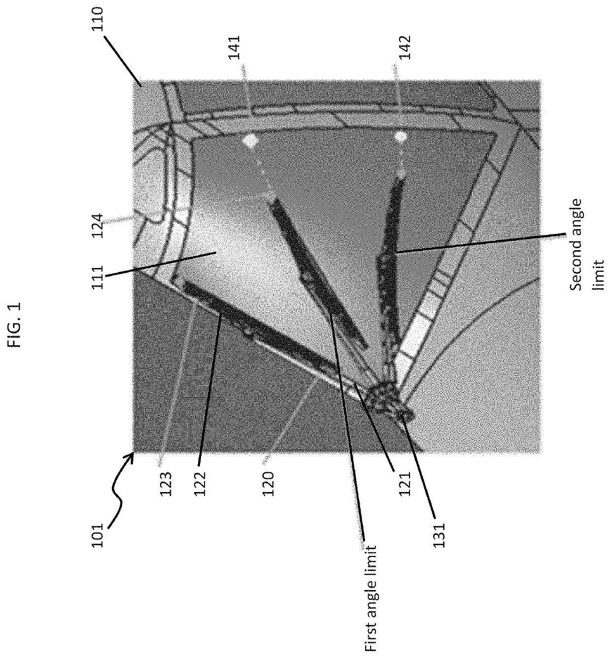
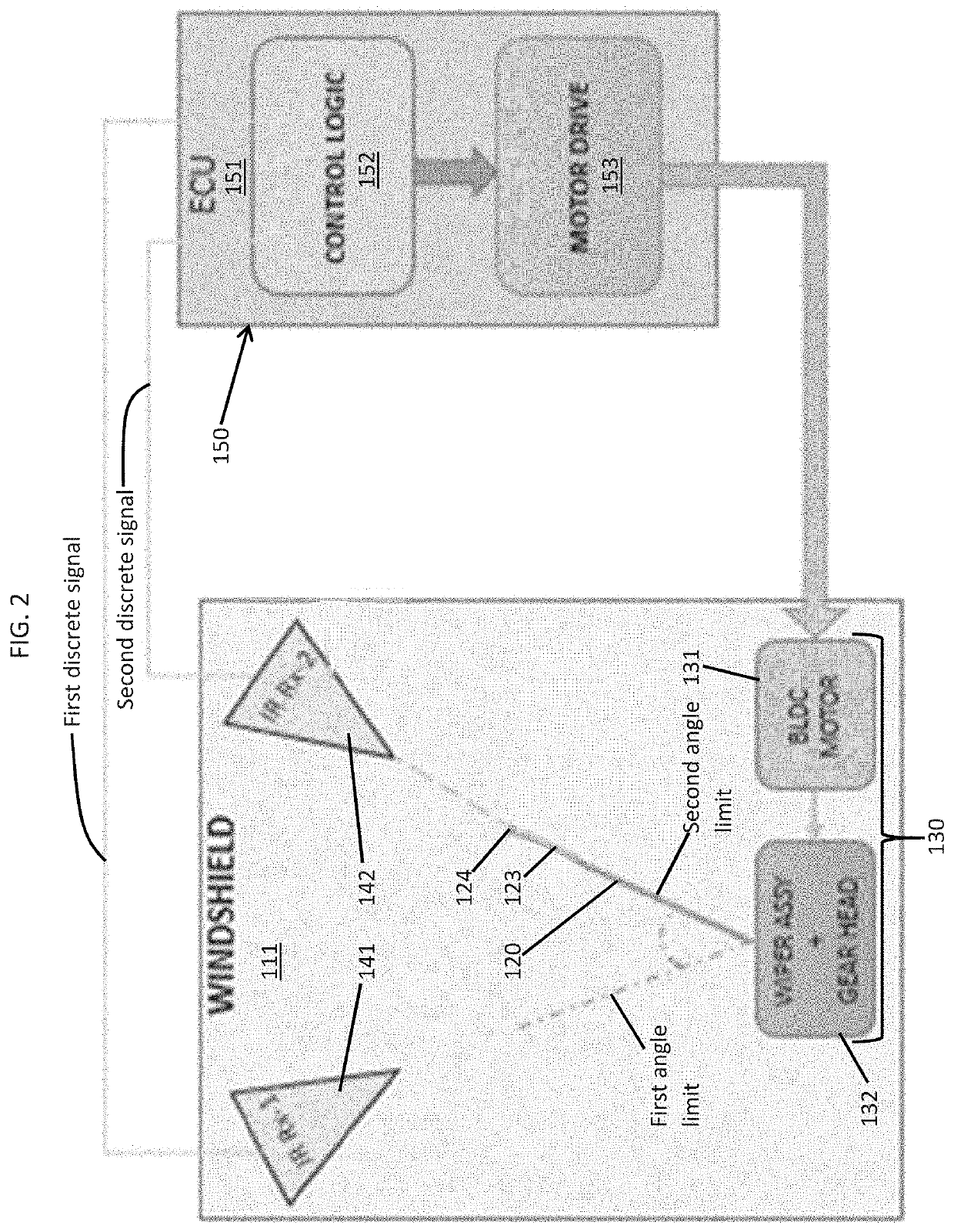
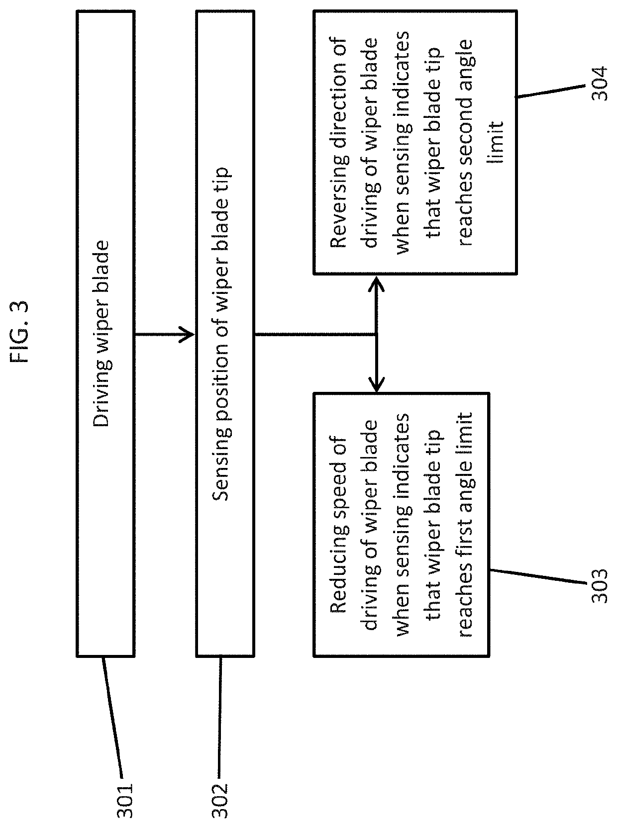
[0031]As will be described below, a WWS is provided in which the problem of over sweep is addressed by placing sensors on a tip of a wiper blade and on a windshield. The sensors can allow for sensing an actual position of the tip of a wiper blade on the windshield based on readings of the sensors. Such readings can be used to control sweep limits of the wiper blade on the windshield.
[0032]With reference to FIGS. 1 and 2, a windshield wiper system (WWS) 101 is provided for use with an airframe 110, such as an airframe of a vehicle or an aircraft, a windshield 111 that is supported in the airframe 110 and a wiper blade 120. The WWS 101 further includes a motor assembly 130 (see FIG. 2), a first sensor 141, a second sensor 142 and a control system 150 (see FIG. 2).
[0033]The wiper blade 120 includes a wiper arm 121 and a wiper blade element 122. The wiper blade element 122 is attached to a distal end of the wiper arm 121 and is biased toward and onto the windshield 111 by the wiper arm ...
PUM
 Abstract
Description
Claims
Application Information