Parts cleaning machine

a cleaning machine and parts technology, applied in the direction of cleaning processes and utensils, cleaning using liquids, chemistry apparatus and processes, etc., can solve the problems of affecting the cleaning effect of parts, causing rashes on any of the workman's exposed skin, and consuming time and labor

Inactive Publication Date: 2021-01-28
ROSE HEINZ
View PDF0 Cites 0 Cited by
  • Summary
  • Abstract
  • Description
  • Claims
  • Application Information

AI Technical Summary

Benefits of technology

[0004]In general terms, a parts cleaning machine is disclosed that is configured to automatically clean a large number of just-manufactured parts (e.g., pins) that are covered with lubricants and other coatings during their manufacture. The parts cleaning machine includes a housing that sits on a reservoir that is filled with a cleaning solution. A parts feeder tube extends horizontally through the housing between a parts entry receiver at which the parts to be cleaned are fed one at a time into the machine and a parts exit cylinder at which clean parts leave the machine. The parts feeder tube includes a pair of arcuate guide rails that face one another so that the parts are pushed in a serial string through the parts cleaning machine along a feedthrough channel between the pair of guide rails of the feeder tube. A series of vertical ribs are spaced from one another along the feeder tube to prevent the parts from tilting out of their alignment with the feedthrough channel.

Problems solved by technology

Because of the caustic nature of the cleaning solution within which his hands are submerged, the workman is often subjected to harsh chemicals and / or gases which have been known to cause illness and induce rashes on any of the workman's exposed skin.
What is more, the conventional process for cleaning parts by hand is often tedious and time consuming, especially when many parts are to be handled.

Method used


Image

  • Parts cleaning machine
  • Parts cleaning machine
  • Parts cleaning machine

Examples


Embodiment Construction

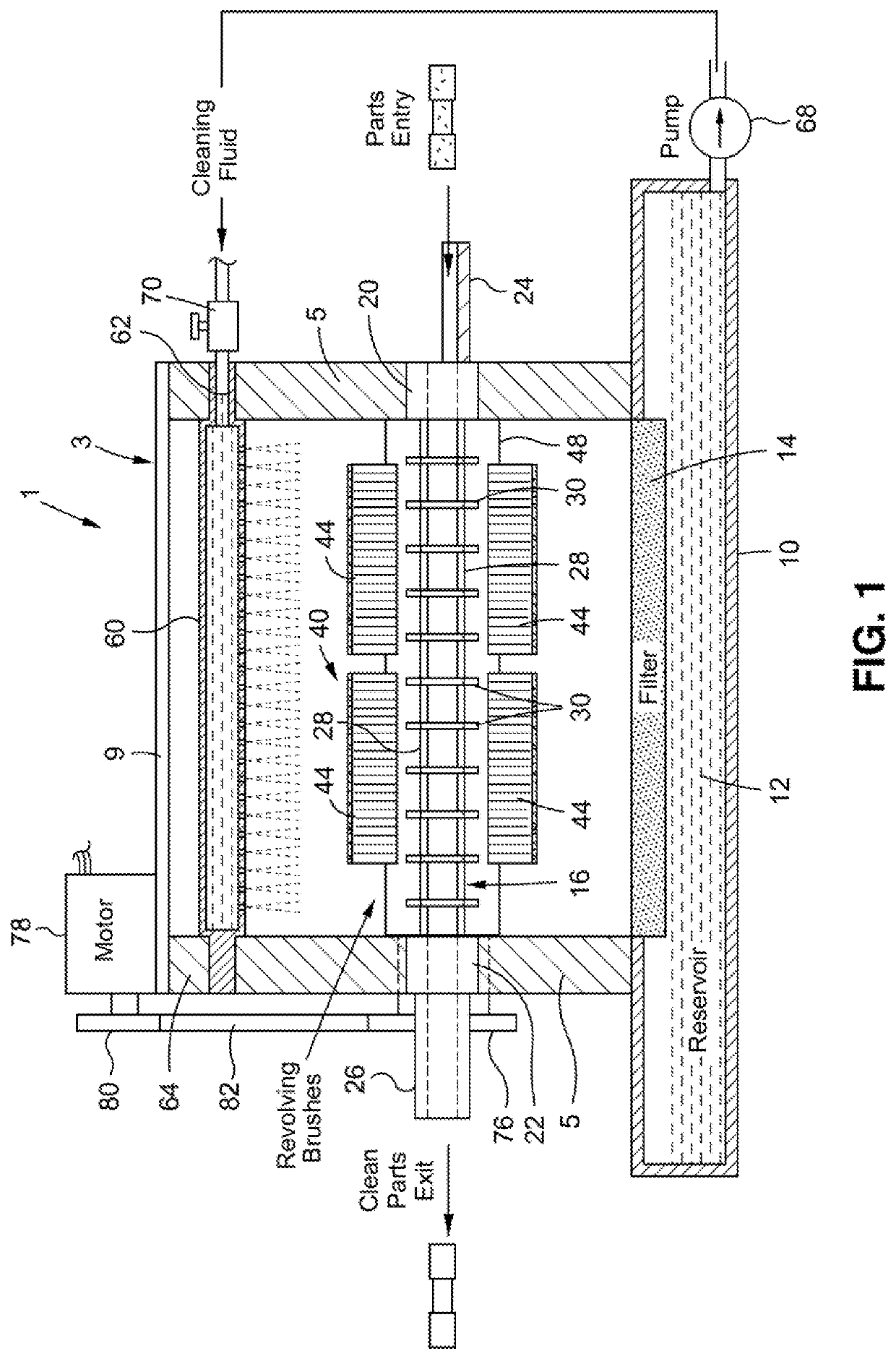
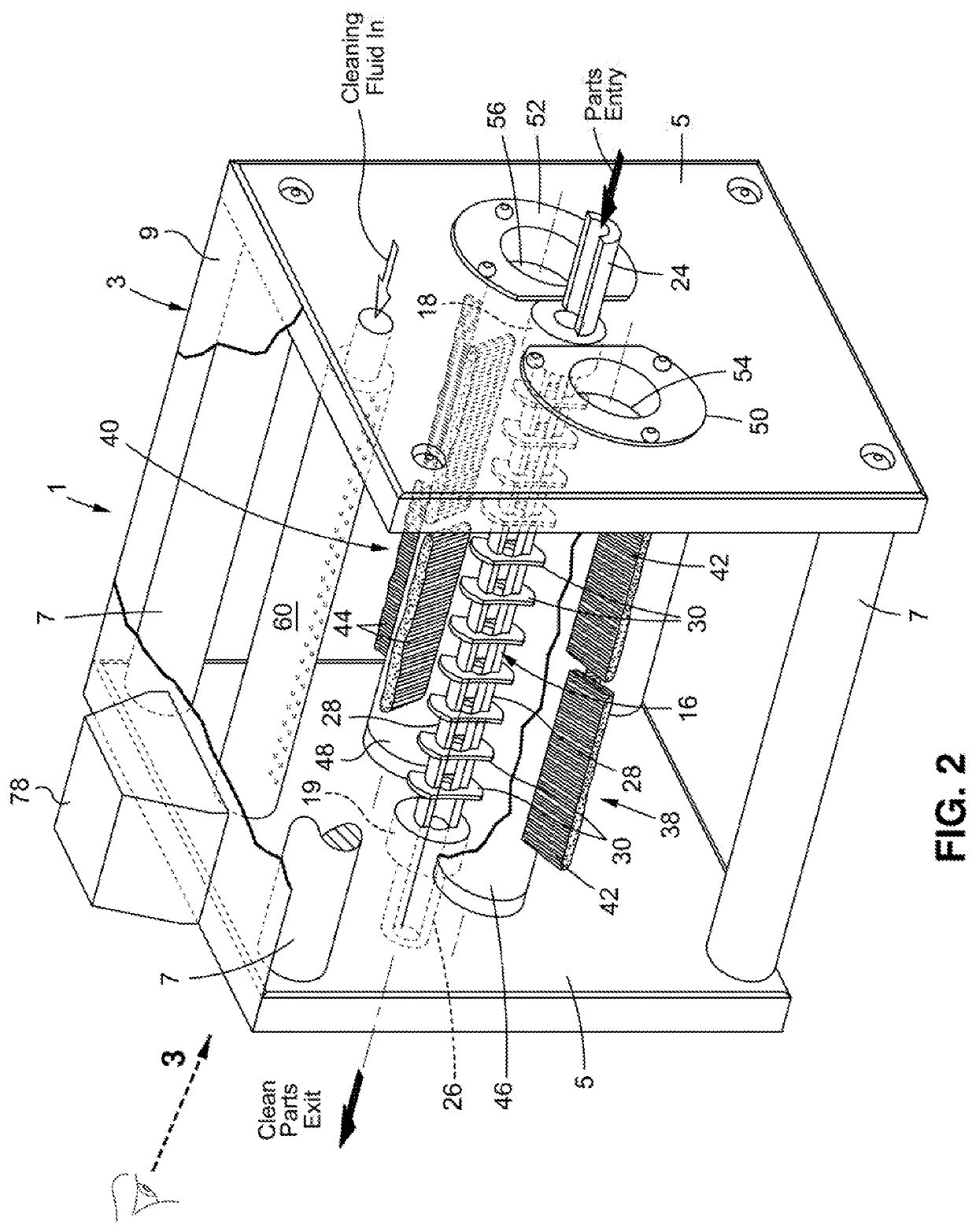
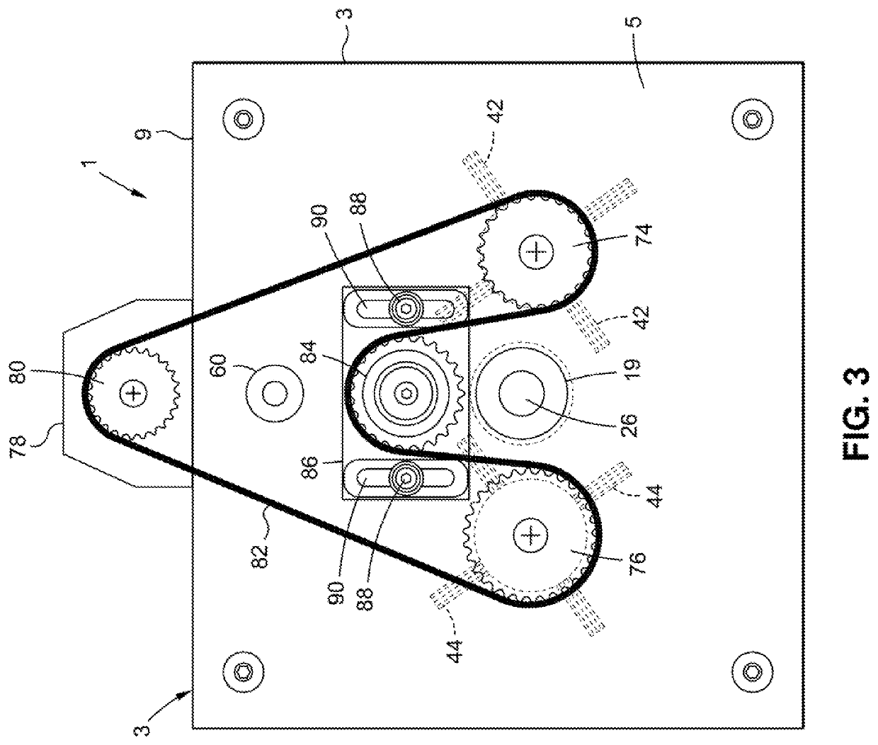
[0015]Details of a parts cleaning machine 1 according to a preferred embodiment of this invention are disclosed while referring initially to FIGS. 1 and 2 of the drawings. The parts cleaning machine 1 has particular application for automatically cleaning a large number of small mechanical parts following their manufacture. That is, the parts cleaning machine 1 herein described is especially adapted to reliably remove lubricants and other coatings with which mechanical parts are covered during their manufacturing process. By way of example only, the small mechanical parts that are ideal for cleaning by means of this invention are those commonly associated with the aircraft, automotive and medical industries to name but a few. However, it is to be understood that the particular size and type of part that is cleaned by the parts cleaning machine 1 are not to be considered a limitation as to the scope of this invention.

[0016]The parts cleaning machine 1 includes a housing 3 into which t...


PUM


Abstract

A parts cleaning machine to automatically clean just-manufactured parts (e.g., pins). The machine includes a housing and a parts guide (e.g., a tube) extending through the housing along which the parts to be cleaned are moved. A pair of brush assemblies extend through the housing at opposite sides of the parts guide. The brush assemblies have rows of bristles that are positioned to engage the parts to be cleaned that move along the parts guide. A cleaning solution manifold is located in the housing to apply cleaning solution supplied thereto from a cleaning solution reservoir to the bristles of the brush assemblies. A motor is coupled to each of the pair of the pair of brush assemblies to cause the brush assemblies to rotate so that the parts are scrubbed with the cleaning solution applied to bristles thereof. One of the pair of brush assemblies is rotated faster than the other.

Description

BACKGROUND OF THE INVENTION1. Field of the Invention[0001]This invention relates to a parts cleaning machine that is configured to automatically remove lubricants and similar coatings from just-manufactured parts (e.g., pins) that are fed one at a time into the machine. The parts cleaning machine includes a pair of motor driven revolving brush assemblies to which a cleaning solution is applied from an overhead cleaning solution manifold so that rows of brushes from the brush assemblies are rotated into engagement with the parts to be cleaned as the parts move through the machine.2. Background Art[0002]Mechanical parts that are manufactured are frequently covered with grease, solvents, oils and other coatings to facilitate the manufacturing process by reducing heat that is generated as a consequence of friction. Once the manufacturing process is completed, the parts must be cleaned to remove the lubricants and the other coatings with which they are covered. A common method to clean t...

Claims


Application Information

Patent Timeline
Patent Type & Authority Applications(United States)
IPC IPC(8): B08B3/04B08B13/00B08B3/02B08B1/00B08B1/02B08B1/04
CPCB08B3/041B08B13/00B08B1/04B08B1/002B08B1/02B08B3/022
Inventor ROSE, HEINZ
Owner ROSE HEINZ
Why Eureka
Try Eureka