Engine lubrication system

Active Publication Date: 2021-01-28
MAZDA MOTOR CORP
View PDF0 Cites 1 Cited by
  • Summary
  • Abstract
  • Description
  • Claims
  • Application Information

AI Technical Summary

Benefits of technology

The purpose of this patent is to create an engine lubrication system that can ensure the amount of oil needed to cool the piston is always available, regardless of the operating situation. The system uses the existing gear shift function of the automatic transmission to secure the necessary oil amount. This ensures the engine runs at its best possible condition, reducing wear and tear and improving overall efficiency.

Problems solved by technology

Thus, when the hydraulic pressure is excessively high, a flow speed of the lubrication oil becomes excessively high, which causes the lubrication oil to spread in the form of a fine mist.
On the other hand, when the hydraulic pressure is excessively low, the flow speed of the lubrication oil is reduced, and thus an amount of the injection oil that is required to cool the piston cannot be sprayed.
As a result, cooling efficiency is degraded.
In the case where an engine speed is low, the oil pump cannot generate the hydraulic pressure that is equal to or higher than the actuation pressure of the oil jet mechanism even when the requested hydraulic pressure is set to be higher than the actuation pressure of the oil jet mechanism, and thus the amount of the injection oil that is required to cool the piston may not be secured.
Thus, it is difficult to secure the amount of the injection oil that is required to cool the piston.
Thus, when the oil temperature is high at the same engine speed, it is not easy to generate the hydraulic pressure that is equal to or higher than the actuation pressure of the oil jet mechanism.
Thus, it is difficult to diffuse heat of the iron piston, and cooling of such a piston tends to be insufficient.
As it has been described so far, depending on an engine operating situation such as the engine speed and the oil temperature, the hydraulic pressure of the oil that is injected by the oil jet mechanism cannot be secured.
Thus, it is impossible to exert a sufficient cooling function.

Method used


Image

  • Engine lubrication system
  • Engine lubrication system
  • Engine lubrication system

Examples


first embodiment

[0028]A description will hereinafter be made on a first embodiment of the present disclosure with reference to FIG. 1 to FIG. 5.

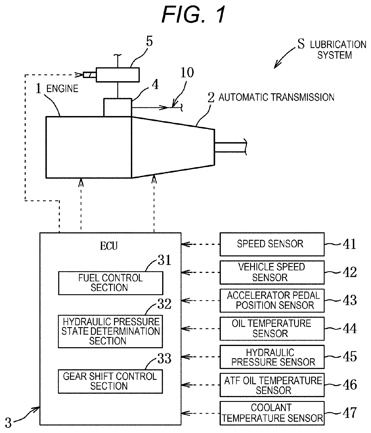
[0029]As illustrated in FIG. 1, an engine lubrication system S (a lubrication device) according to this first embodiment includes, as main components, an engine 1 as a six-cylinder diesel engine, an automatic transmission 2, an electronic control unit (ECU) 3 (control means) for integrally controlling the lubrication system S, various sensors 41 to 47, and the like, for example. Optionally, the ECU may include the processor 835 and other circuitry in system 800 of FIG. 8, which may be implemented as a single processor-based system, or a distributed processor based system.

[0030]First, a description will be made on the engine 1.

[0031]In the engine 1, a cylinder head, a cylinder block, a crankcase, and an oil pan that collects and stores lubrication oil are vertically coupled to each other, and pistons, each of which is made of iron and can slide in respective...

second embodiment

[0089]Next, a description will be made on a lubrication system SA according to a second embodiment with reference to FIG. 6.

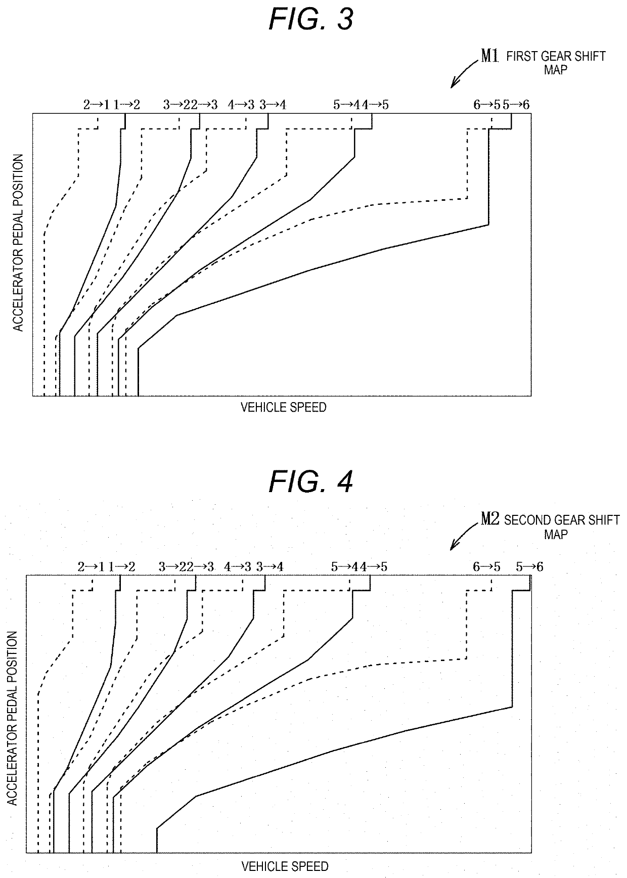
[0090]In the first embodiment, the entire sixth gear shift line for the shift-up to the sixth gear has the completely different patterns in the first gear shift map M1 selected during the normal travel and the second gear shift map M2 selected in the hydraulic pressure insufficient state. In the second embodiment, the sixth gear shift line has partially different patterns in the first gear shift map M1 and a second gear shift map M3.

[0091]As illustrated in FIG. 6, in the second gear shift map M3, gear shift lines that define the shift-ups (solid lines) from the first gear to the sixth gear and gear shift lines that define the shift-downs (broken lines) in the hydraulic pressure insufficient state are set. The sixth gear shift line in the second gear shift map M3 is set by partially shifting a low-load range of the sixth gear shift line in the first gear shift m...


PUM


Abstract

An engine lubrication system including: an oil pump configured to be driven by an engine; an oil jet mechanism configured to inject oil pressure-fed by the oil pump to a piston; and circuitry configured to set a target hydraulic pressure of the oil injected from the oil jet mechanism according to an operation state of the engine; determine a hydraulic pressure state of the oil injected from the oil jet mechanism; and change a gear stage of the automatic transmission to a lower gear stage in a case that a predetermined condition between the determined hydraulic pressure state and the target hydraulic pressure is satisfied.

Description

CROSS-REFERENCE TO RELATED APPLICATION[0001]The present application claims priority to JP 2019-136839, filed Jul. 25, 2019, the entire contents of which are incorporated herein by reference.TECHNICAL FIELD[0002]The present disclosure relates to an engine lubrication system and, in particular, to an engine lubrication system capable of setting a target hydraulic pressure of oil that is injected by an oil jet mechanism according to an operation state of an engine.BACKGROUND ART[0003]Conventionally, for a purpose of preventing burning and strength degradation of a piston that contacts high-temperature combustion gas, an oil jet mechanism that suppresses a temperature increase of the piston by spraying engine lubrication oil onto a piston inner surface from a connecting rod side has been known.[0004]Such an oil jet mechanism sprays the lubrication oil that is pressure-fed from an oil pump on the piston inner surface using a hydraulic pressure. Thus, when the hydraulic pressure is excess...

Claims


Application Information

Patent Timeline
IPC IPC(8): B60W30/184F01M1/02F01M1/08B60W10/10B60W10/06F16H61/02F16H59/78F16H59/72
CPCB60W30/184F01M1/02F01M1/08B60W10/10B60W10/06F16H61/0213F16H2061/0227F16H59/72F01M2001/0253F01M2250/60B60W2510/1005B60W2510/1075B60W2510/0676F16H59/78F16H2061/0232F16H61/16F01M2001/0246F01M2001/0238
Inventor HONDA, KENTAHASHIMOTO, MASANORIFUKUDA, DAISUKEYAMADA, ATSUSHISHIMO, DAISUKE
Owner MAZDA MOTOR CORP
Why Eureka
Try Eureka