Loop heat pipe structure
- Summary
- Abstract
- Description
- Claims
- Application Information
AI Technical Summary
Benefits of technology
Problems solved by technology
Method used
Image

Examples
first embodiment
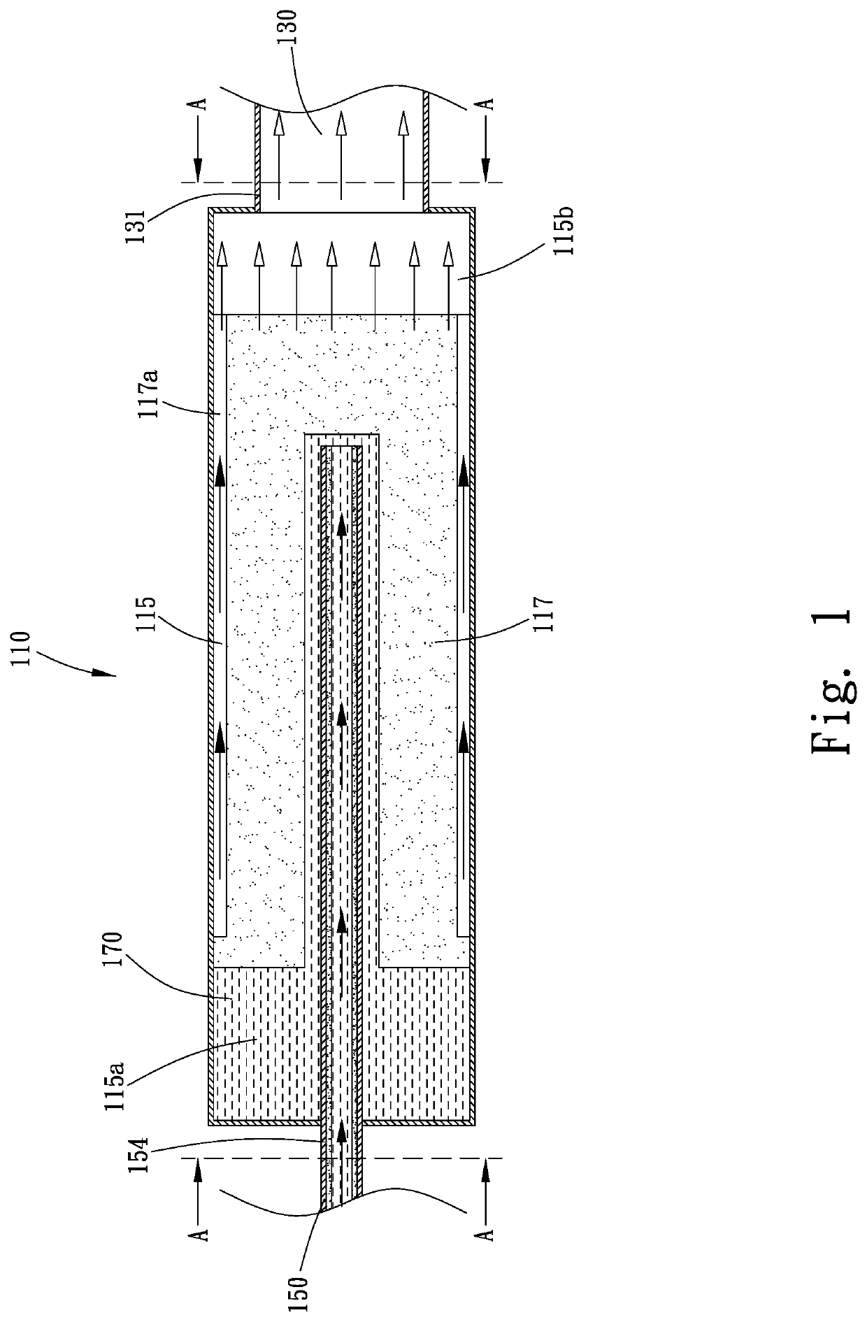
[0031]The evaporator 110 internally defines a vaporization chamber 115, in which a first wick structure 117 is provided and a working fluid 170 is filled. In the illustrated first embodiment, the first wick structure 117 separates the vaporization chamber 115 into a liquid chamber 115a and a vapor chamber 115b. The liquid chamber 115a is located adjacent to the at least one liquid pipe 150 and stores the working fluid 170 that is in a liquid phase. The vapor chamber 115b is located adjacent to the at least one vapor pipe 130 and allows the working fluid 170 in a gas phase to flow therethrough. The first wick structure 117 includes a plurality of grooves 117a, via which the gas-phase working fluid 170 flows to the vapor chamber 115b.
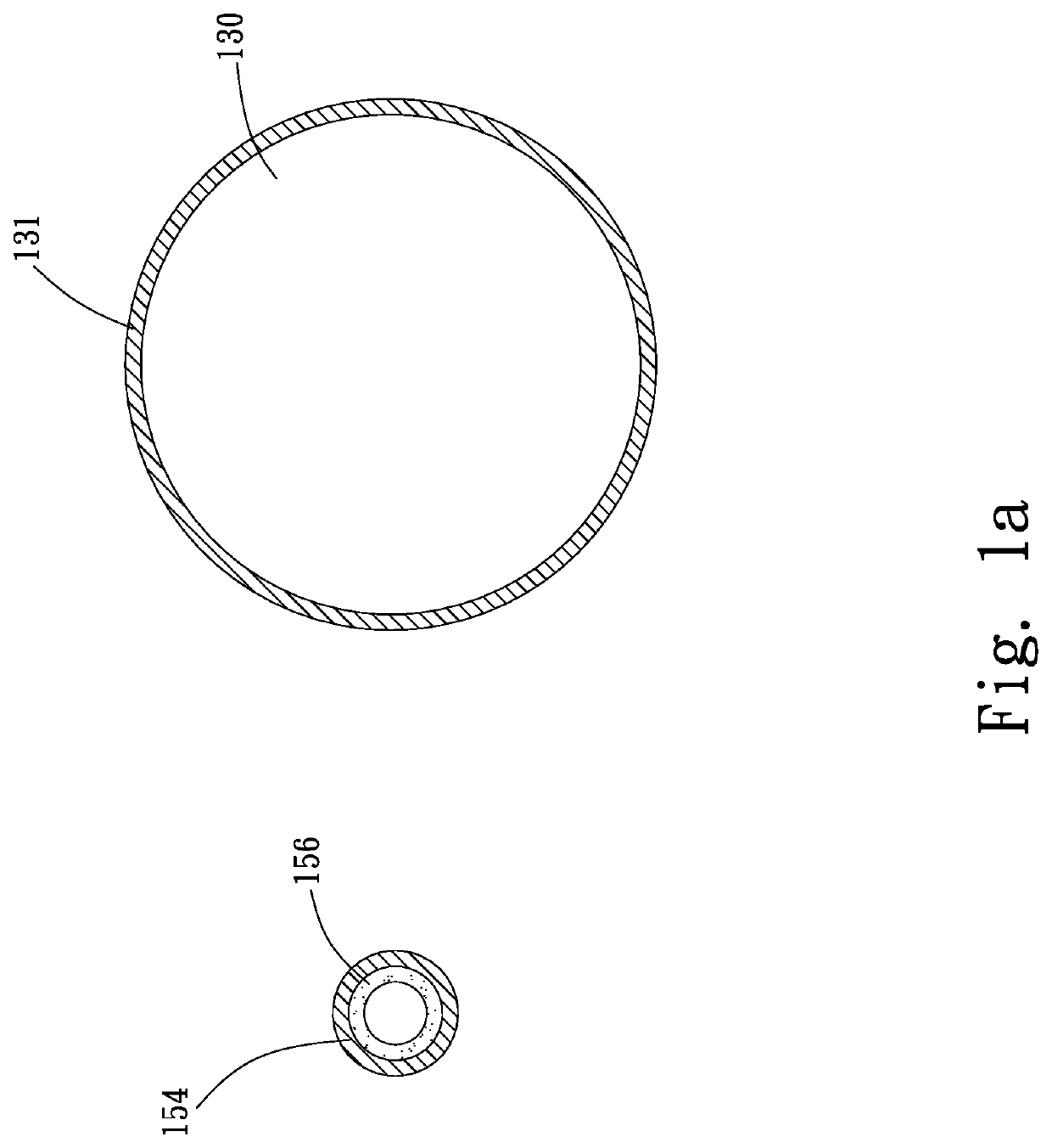
[0032]The at least one vapor pipe 130 has a first end 131 and a second end 133 located at two opposite ends of the vapor pipe 130. The first end 131 of the vapor pipe 130 is communicable with an end of the vaporization chamber 115 of the evaporator 110 h...
second embodiment
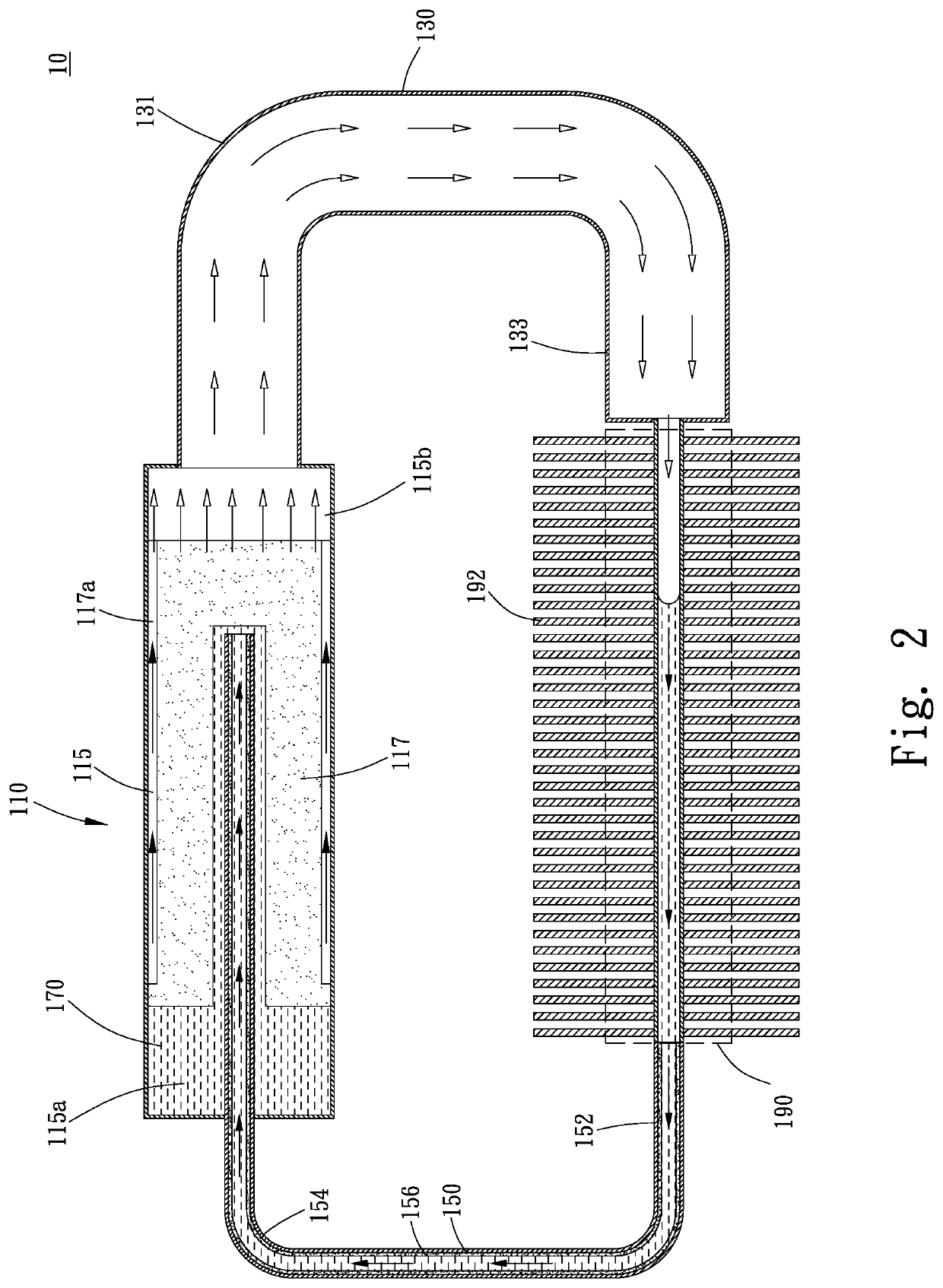
[0038]Further, in the illustrated second embodiment, the condensing section 190 is internally provided with a third wick structure 196, which is capillarily connected to the second wick structure 156. Herein, the description “is capillarily connected to” means the second and the third wick structure 156, 196 are in material contact or connection with each other, such that pores in the second wick structure 156 are communicable with pores in the third wick structure 196 and a capillary force of the third wick structure 196 can be transmitted or extended to the second wick structure 156, enabling the liquid-phase working fluid 170 to flow from the condensing section 190 back to the liquid chamber 115a due to the capillary force.
[0039]The condensation chamber 194 can receive and cool more gas-phase working fluid 170 at a time, and the capillary force of the second and third wick structures 156, 196 enables the liquid-phase working fluid 170 to more quickly flow back to the liquid chamb...
sixth embodiment
[0047]As can be seen in FIG. 8a, in the illustrated sixth embodiment, a grand total of the cross-sectional areas of the vapor pipes 130 is larger than the total cross-sectional area of the one single liquid pipe 150.
[0048]With the plurality of vapor pipes 130, an increased amount of gas-phase working fluid 170 can be guided out of the evaporator 110 into the condensation chamber 194 for cooling, enabling the loop heat pipe structure 10 of the present invention to have largely upgraded heat dissipation effect.
[0049]FIG. 9 is a sectional top view of a loop heat pipe structure 10 according to a seventh embodiment of the present invention, and FIG. 9a includes sectional views taken along two lines C-C of FIG. 9, showing the cross-sectional areas of a plurality of vapor pipes 130 and the cross-sectional areas of a plurality of liquid pipes 150 of the loop heat pipe structure 10 according to the seventh embodiment of the present invention. Please refer to FIGS. 9 and 9a along with FIG. 8....
PUM
 Abstract
Description
Claims
Application Information
 - R&D Engineer
- R&D Manager
- IP Professional
- Industry Leading Data Capabilities
- Powerful AI technology
- Patent DNA Extraction
Browse by: Latest US Patents, China's latest patents, Technical Efficacy Thesaurus, Application Domain, Technology Topic.
© 2024 PatSnap. All rights reserved.Legal|Privacy policy|Modern Slavery Act Transparency Statement|Sitemap