Cooling fan rack

a fan rack and cooling fan technology, applied in indirect heat exchangers, semiconductor/solid-state device details, lighting and heating apparatus, etc., can solve the problems of reducing the working efficiency or damage of electronic devices, reducing the heat dissipation effect of heat dissipating units alone, and reducing the overall volume. , the effect of reducing the volum

Inactive Publication Date: 2013-08-13
ASIA VITAL COMPONENTS (CHINA) CO LTD
View PDF11 Cites 5 Cited by
  • Summary
  • Abstract
  • Description
  • Claims
  • Application Information

AI Technical Summary

Benefits of technology

[0007]Another object of the present invention is to provide a cooling fan rack that has a structure allowing a radiating fin assembly assembled thereto to have a reduced volume and accordingly reduced material cost.
[0008]To achieve the above and other objects, the cooling fan tack according to the present invention is designed for connecting to a thermal module. The cooling fan rack includes a frame defining a union section; a plurality of stoppers arranged in the frame, the stoppers and the frame together defining an accommodating space for receiving part of the thermal module therein; and a plurality of airflow paths formed between two adjacent stoppers to communicate with the accommodating space and adjoin two opposite ends of the thermal module. The frame is provided at two lateral lower sides with a notch each, which communicate an external environment with the accommodating space. The thermal module includes a radiating fin assembly and a cooling fan. The two notches on the frame are sized for separately straddling two upper outer sides of the radiating fin assembly, so that an upper portion of the radiating fin assembly is received in the accommodating space. With the notches, the radiating fin assembly can be firmly fitted in the cooling fan rack while only having a reduced overall volume. The cooling fan is firmly fitted in the union section to downward press against the stoppers. While part of the cooling airflow produced by the cooling fan flows into the radiating fin assembly, the remaining part of the cooling airflow can flow through the airflow paths formed between the adjacent stoppers to two opposite ends of the radiating fin assembly. Therefore, an upgraded heat dissipation effect can be achieved.
[0009]In brief, the cooling fan rack of the present invention has the following advantages: (1) assisting the thermal module in providing good heat dissipation effect; (2) allowing the radiating fan assembly to have a reduced size to save material therefor; (3) allowing the thermal module to be manufactured at reduced cost; and (4) helping in overcoming the problem of accumulated heat at the central portion of the thermal module.

Problems solved by technology

When an electronic device operates, internal electronic elements thereof will produce a large amount of heat.
Thus, an additional heat dissipating unit is required to enhance heat dissipation of the electronic device, lest the electronic device should have lowered working efficiency or become damaged due to overheating.
However, the heat dissipation effect of the heat dissipating unit alone is limited.
This is of course inconvenient to do so.
In brief, the thermal module with the conventional cooling fan 2 and heat dissipating unit 1 has the following disadvantages: (1) being subject to accumulation of heat; (2) having low heat dissipation effect; and (3) requiring higher manufacturing cost.

Method used


Image

  • Cooling fan rack
  • Cooling fan rack
  • Cooling fan rack

Examples


Embodiment Construction

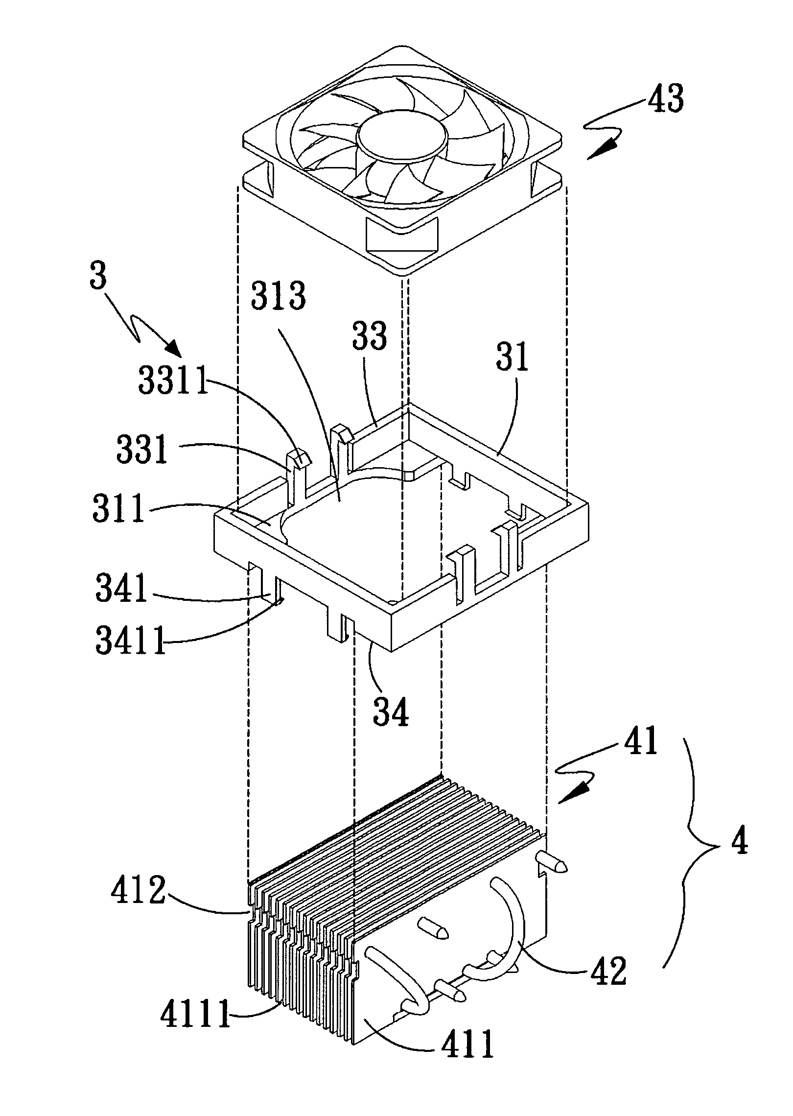
[0018]Please refer to FIGS. 2 through 6. A cooling fan rack 3 according to a preferred embodiment of the present invention as shown in FIG. 2 is designed for connecting to a thermal module 4.

[0019]The cooling fan rack 3 includes a frame 31 defining a union section 32; at least one stopper 311 located at a corner in the frame 31, in the illustrated preferred embodiment, there are four stoppers 311 separately located at four corners in the frame 31, and the stoppers 311 and the frame 31 together defining an accommodating space 312 for receiving an upper portion of a radiating fin assembly 41 of the thermal module 4 therein; and at least one airflow path 313 formed between two adjacent stoppers 311 to communicate with the accommodating space 312 and adjoin two opposite ends of the radiating fin assembly 41. The frame 31 is formed at two lateral lower sides with at least one first notch 314 and one second opening 315, which communicate with the accommodating space 312.

[0020]The thermal ...


PUM


Abstract

A cooling fan rack includes a frame defining a union section; a plurality of stoppers arranged at four corners in the frame to cooperate with the frame to define an accommodating space; and a plurality of airflow paths formed between two adjacent stoppers to communicate with the accommodating space. The frame is provided at two lateral lower sides with a notch each, which communicate with the accommodating space. The two notches are sized for straddling two upper outer sides of a radiating fin assembly, so that the radiating fin assembly with a reduced volume can be upward fitly received in the accommodating space. A cooling fan is downward firmly fitted in the union section. Part of the cooling airflow produced by the cooling fan can flow through the airflow paths to two opposite ends of the radiating fin assembly, enabling upgraded heat dissipation effect.

Description

FIELD OF THE INVENTION[0001]The present invention relates to a cooling fan rack, and more particularly to a cooling fan rack that enables part of the cooling airflow produced by a cooling fan fitted to an upper side of the rack to flow toward two opposite ends of a radiating fin assembly assembled to a lower side of the rack.BACKGROUND OF THE INVENTION[0002]When an electronic device operates, internal electronic elements thereof will produce a large amount of heat. Thus, an additional heat dissipating unit is required to enhance heat dissipation of the electronic device, lest the electronic device should have lowered working efficiency or become damaged due to overheating. The heat dissipating unit is usually a radiating fin assembly or a heat sink. However, the heat dissipation effect of the heat dissipating unit alone is limited. Normally, at least one cooling fan is further assembled to the heat dissipating unit, so that the cooling fan produces cooling airflow toward the heat di...

Claims


Application Information

Patent Timeline
Patent Type & Authority Patents(United States)
IPC IPC(8): F28F7/00H05K7/20
CPCF28D15/0275H01L23/427H01L23/467H01L2924/0002H01L2924/00
Inventor LIN, SHENG-HUANG
Owner ASIA VITAL COMPONENTS (CHINA) CO LTD
Why Eureka
Try Eureka