

Improved touch-sensing apparatus
- Summary
- Abstract
- Description
- Claims
- Application Information
AI Technical Summary
Benefits of technology
Problems solved by technology
Method used
Image

Examples
Embodiment Construction
[0031]In the following, embodiments of the present invention will be presented for a specific example of a touch-sensitive apparatus. Throughout the description, the same reference numerals are used to identify corresponding elements.
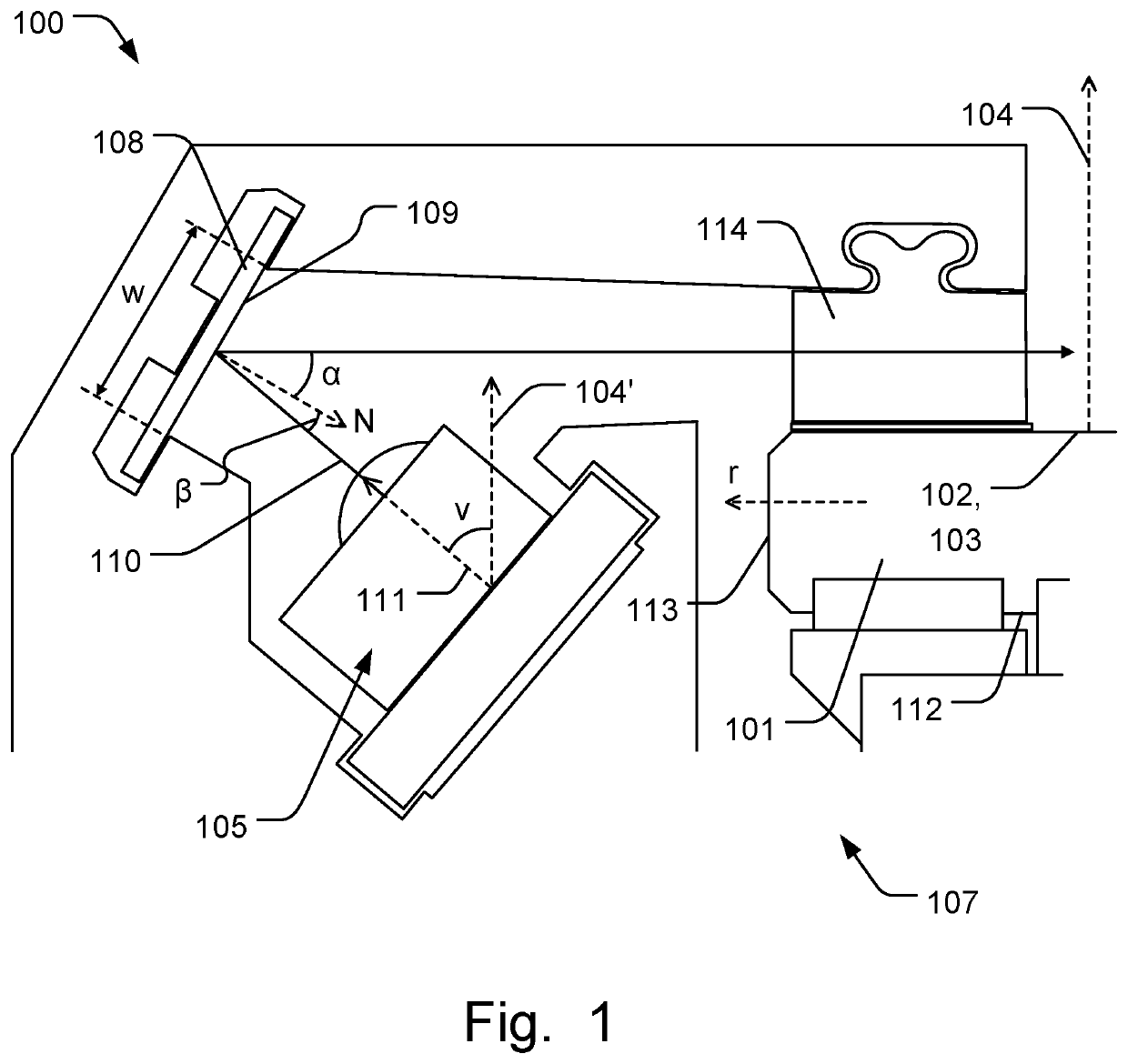
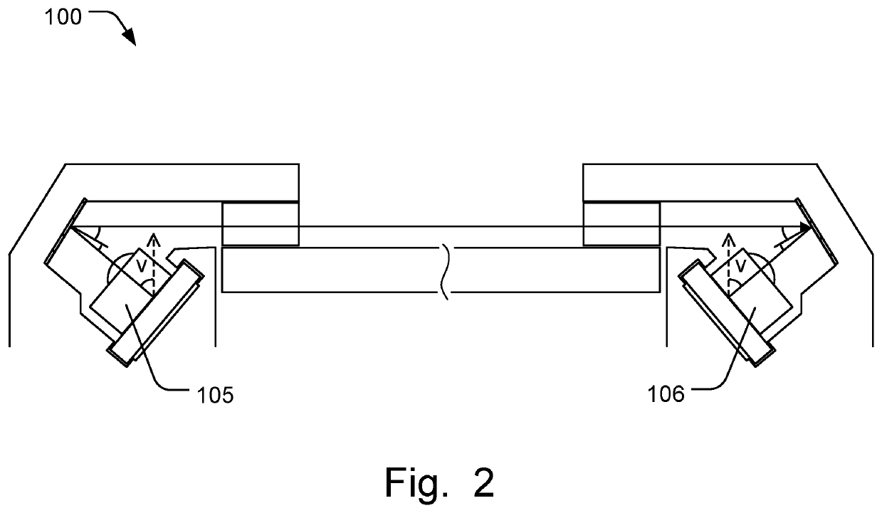
[0032]FIG. 1 is a schematic illustration of a touch-sensing apparatus 100 comprising a panel 101 that defines a touch surface 102 extending in a plane 103 having a normal axis 104. The panel 101 is a light transmissive panel in one example. The touch-sensing apparatus 100 comprises a plurality of emitters 105 and detectors 106 arranged along a perimeter 107 of the panel 101. FIG. 1 shows only an emitter 105 for clarity of presentation, while FIG. 2 illustrates how light is transmitted from an emitter 105 to a detector 106 across the touch surface 102. The touch-sensing apparatus 100 comprises a light directing element 108 arranged adjacent and along the perimeter 107. The light directing element 108 comprises a light directing surface 109. The emitters ...
PUM
 Abstract
Description
Claims
Application Information