Large scale flywheel for energy storage

Active Publication Date: 2020-12-24
BERGAN TECH AS
View PDF0 Cites 3 Cited by
  • Summary
  • Abstract
  • Description
  • Claims
  • Application Information

AI Technical Summary

Benefits of technology

The rotor design of this patent is made of strong, high-strength material combined with a filler material. The filler material fills the voids of the load bearing structure. The goal is to reduce energy loss from friction as much as possible. This can be achieved by controlling humidity and air pressure inside the rotor chamber, which can be done by fully separating the flywheel chamber from the surroundings using a strong barrier. The invention also mentions that reducing air pressure inside the rotor can lead to a better reduction in surface friction loss.

Problems solved by technology

There are a series of challenges associated with flywheel energy storage.
First of all, there is an unavoidable loss of energy due to friction between the rotor and support system as well as from the rotor to the surrounding atmosphere.
Another generic problem is imperfections in mass distribution and geometric misalignments which in turn can lead to vibrations and mechanical wear.
Yet another problem is safety issues stemming from high centrifugal forces which can lead to that the rotor fails in an explosive manner and thereby releases high amounts of kinematic rotary energy and static elastic energy.
Unfortunately, high velocity flywheels made with materials with extreme strength properties correspondingly tend to be extraordinarily expensive.
This means that the total storage energy capacity of such a system is rather limited viewed in a grid scale energy setting.
Looking at the current state of the art it seems clear that flywheel technology has not yet been developed to a stage where it can fully serve as large scale energy storage.
It is clear that none of the solutions described in prior art can provide a practical solution to very large scale energy storage when it is by “large scale” is meant that the energy stored is in order of MW hours and beyond.
Clearly a main issue is to reduce loss of energy through friction within the support system and to the surrounding gas or atmosphere.
Unfortunately, magnetic levitation does not scale up for levitating very heavy rotor masses.
Clearly such an approach brings with it a series of new problems that have to be resolved.
One such problem is that the weight of the rotor may be so large that it cannot be prefabricated, transported and mounted on site.
Another challenge is to provide a new inventive step to minimize the friction associated with support and spinning of a very heavy rotor.
Thirdly, it must be anticipated that it will be necessary to stop the rotor in a controlled way and replace supporting parts that are subjected to wear.
There is one further issue to be mentioned for very large flywheels, and that is the consideration of forces associated with directional change of the very large rotary momentum of the spinning rotor (vector quantity).

Method used


Image

  • Large scale flywheel for energy storage
  • Large scale flywheel for energy storage
  • Large scale flywheel for energy storage

Examples


Embodiment Construction

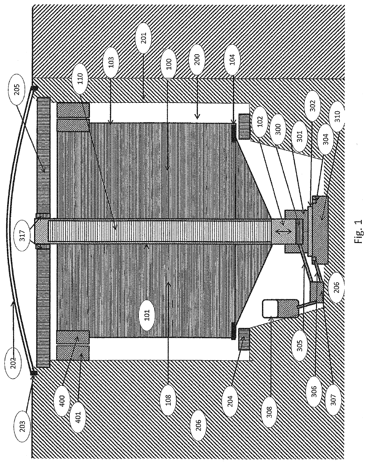
[0126]FIG. 1 illustrates the main parts and principles for the large scale flywheel system according to the present invention. This system may in principle be built above ground whereas in most cases placing the storage in an excavation in the ground 206 may be a better embodiment for safety and other reasons. The storage is contained in a strong structural encasement or housing 201, preferably made of reinforced concrete. This encasement has a removable roof or lid 202 that serves for protection as well as for a seal that enables reduction of the internal pressure in the rotor chamber 200 to be lowered. The roof structure has an air-tight seal 203 along the rim that prevents outside air from leaking into the rotor chamber. There is open access to the entire flywheel system when the roof 202 is removed. Additionally, there is a sealed access 503 to the rotor chamber from outside exemplified in FIG. 9.

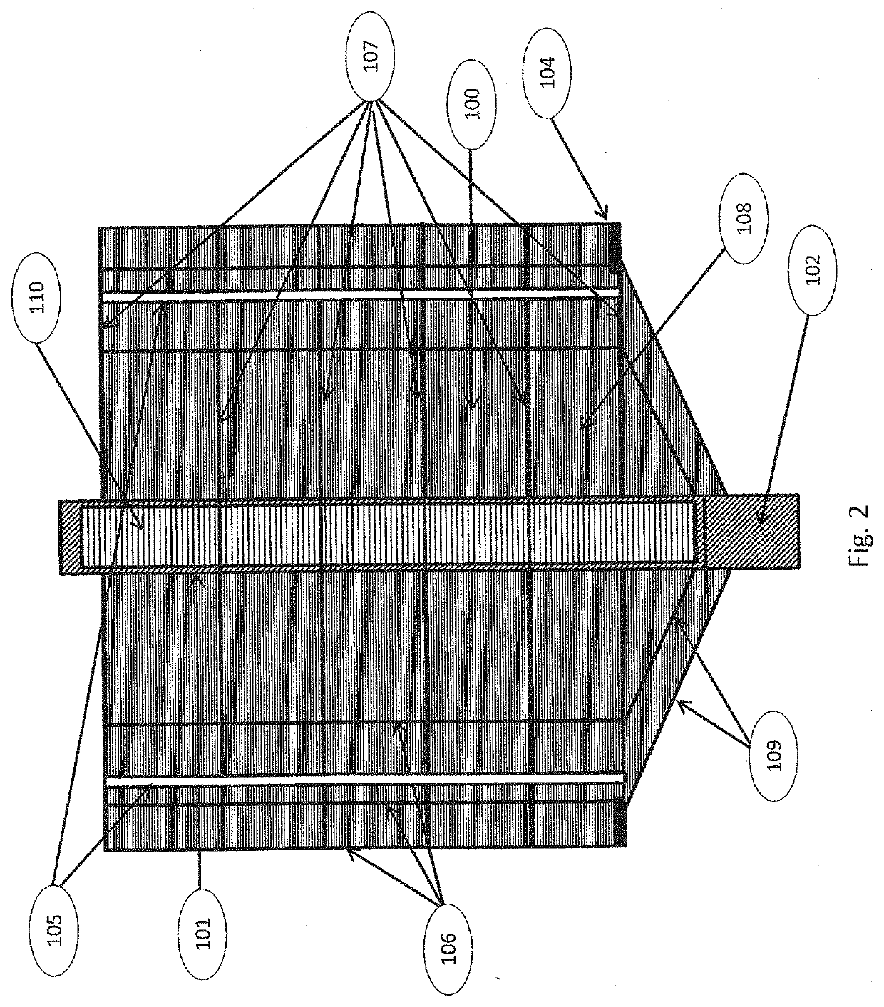
[0127]The rotor of the flywheel 100 is a composite structure made of easily accessi...


PUM


Abstract

Flywheel for energy storage, comprising a rotor, a housing enclosure, means for charging energy by transferring electric energy to stored kinetic energy in the rotating rotor and means for discharging energy by transferring stored kinetic energy in the rotating rotor to electric energy, distinctive in that the rotor is vertically oriented, the rotor has mass of over 5000 kg, the rotor comprises a central vertical shaft, a radial bearing is arranged to an upper end of the vertical shaft, an axial-radial hydraulic bearing, or separate axial and radial bearings, is arranged to a lower end of the vertical shaft.

Description

FIELD OF INVENTION[0001]The present invention relates to energy storages. More specifically, the invention relates to a storage in which the energy is stored in the form of rotary kinetic energy, a system for how to store and extract energy, and a method for building it, a method for how to operate it and replace wearing parts, and the overall use of the storage. The main components of the storage comprise a rotor, a support system for the rotor, electric motors and generators for input and output of electric power, and a hydraulic system that provides low friction support and enables construction, operation and repair of the system. All of this is contained in a chamber for which pressure and overall gaseous condition are controlled.BACKGROUND OF INVENTION AND PRIOR ART[0002]Flywheel type energy storages can be used for stabilizing frequency and current of electric power systems, for storing energy coming from such systems, and for delivering back electric power on demand.[0003]The...

Claims


Application Information

Patent Timeline
IPC IPC(8): H02K7/02F03G3/08F16C32/06H02K7/04H02K7/08
CPCH02K7/04H02K7/085F03G3/08F16C32/0696H02K7/025F16C2361/55F16F15/3156F16C32/06F16C32/0692F16C33/74F16C32/064Y02E60/16
Inventor BERGAN, PÅL G.
Owner BERGAN TECH AS
Why Eureka
Try Eureka