Bone staple drill guide with drill cartridge and compression device
- Summary
- Abstract
- Description
- Claims
- Application Information
AI Technical Summary
Benefits of technology
Problems solved by technology
Method used
Image

Examples
Embodiment Construction
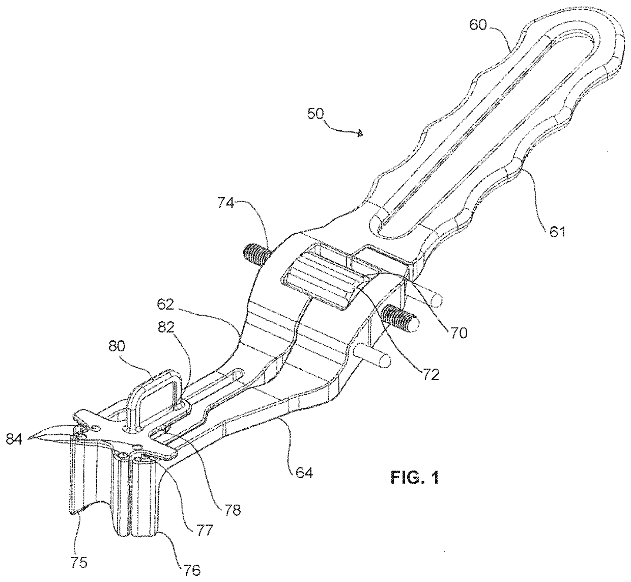
[0011]The present invention comprises a drill guide assembly 50 for use with a room temperature superelastic Nitinol compression staple 10 for bone fixation in the surgical management of fractures and reconstruction of the foot and hand. Typically, the staples used with the present invention have a nominally U-shaped profile with a bridge member 14 spanning a space between opposing legs 12 (and it should be understood that the present inserter is also suitable for use with a staple having four legs in which each end of the bridge member includes a pair of legs, or alternatively, the staple could have three legs with a pair on one end, and a single leg opposing the pair). The drill guide assembly 50 of the invention is illustrated herein for use with a staple having two opposing pairs of legs that are joined by a bridge member of the staple, but it should be understood that the staple has two or more, and preferably 2, 3, or 4 transversely extending legs 1 that will engage bones or b...
PUM
 Abstract
Description
Claims
Application Information
PatSnap Eureka turns technology decisions into work you can execute. Powered by our Innovation Knowledge Graph, it runs expert workflows across engineering, life sciences, materials and intellectual property. Get your review-ready output in minutes.


