Compression bone staple, apparatus and method of the invention

a bone staple and compression bone technology, applied in the field of compression bone staples, apparatus and methods, can solve the problems of difficult manual installation of the clip using hemostats and the like, large surgical openings, and inconvenient use, and achieve the effect of quick application

Inactive Publication Date: 2012-02-02
DALLEN MEDICAL
View PDF8 Cites 35 Cited by
  • Summary
  • Abstract
  • Description
  • Claims
  • Application Information

AI Technical Summary

Problems solved by technology

Unfortunately this method requires the drilling of specially sloped holes, involves multiple steps and is time-consuming, and like the conventional rigid fastening techniques, requires relatively large surgical opening.
Also, the manual installation of the clip using hemostats and the like is difficult, requires meticulous skill and handling.
This design appears inherently limited regarding adjustability and maintenance of constant pressure.
The foregoing techniques involving crimpable clips all appear to be imprecise in setting up suitable compressive' forces, require hole drilling and related problems, and do not lend themselves to minimizing the size of the surgical opening.
Unfortunately there is concern for trauma to the bone due to driving of the compound-shaped legs into the bone mass, and there is little apparent precision in establishing the desired compressive forces.

Method used


Image

  • Compression bone staple, apparatus and method of the invention
  • Compression bone staple, apparatus and method of the invention
  • Compression bone staple, apparatus and method of the invention

Examples


Embodiment Construction

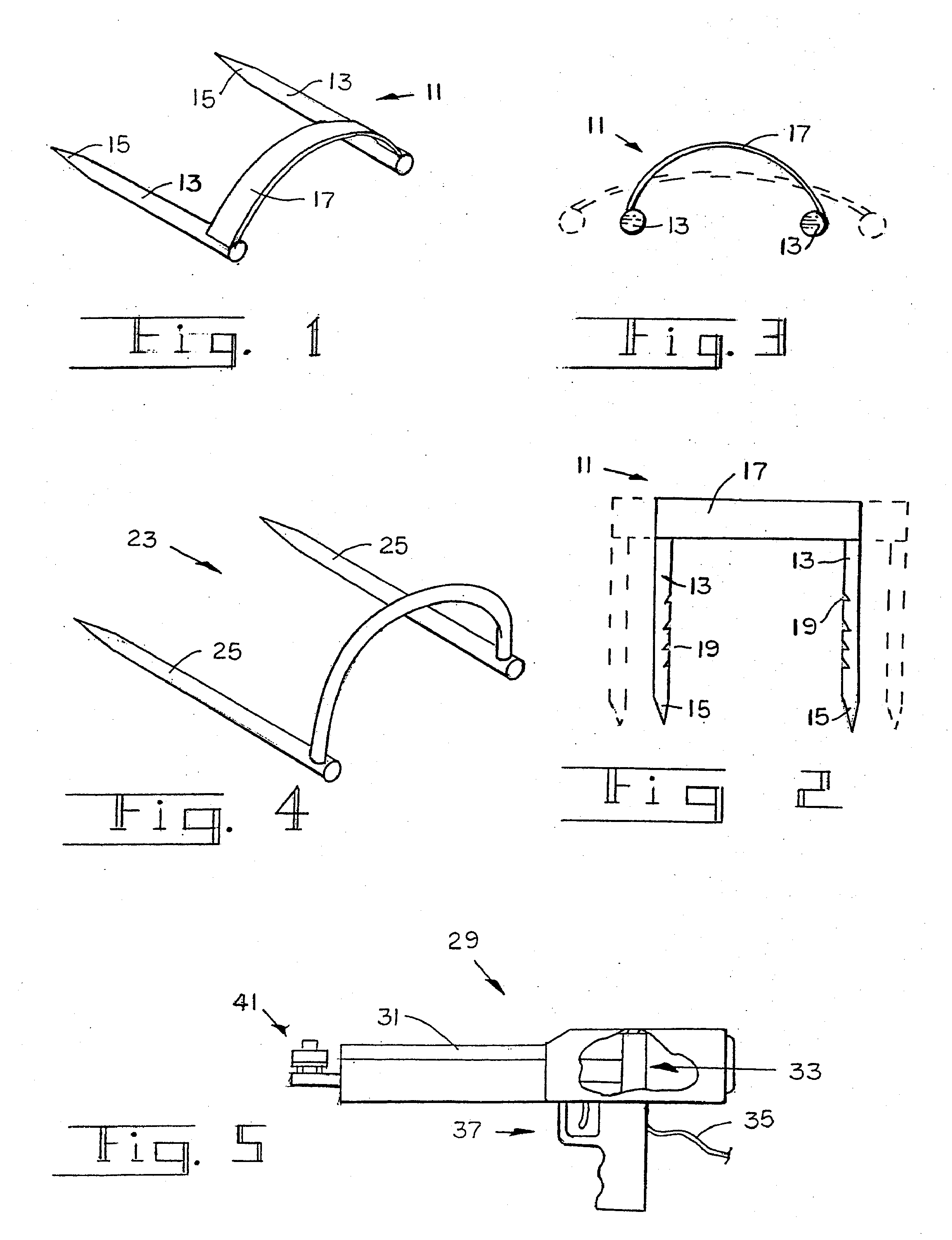
[0058]Referring now the drawings, FIGS. 1-3 show that a preferred embodiment of a compression staple 11 according to the present invention has a pair of legs 13 with sharp front ends 15 and a bridge 17 that interconnects the rear end, portions of legs 13. Staple 11 is fabricated of a surgical grade, bio-compatible metal, such as stainless steel, titanium alloy or other suitable alloy. Bridge 17 functions not only to hold legs 13 in approximate parallel relationship, but is selected to act as a spring by the flexing of its bow when the legs are spread apart as illustrated by the broken line image of FIGS. 2 and 3. This imparts an inward reacting force between the legs proportional to the degree of their displacement. It will be appreciated that the dimensions, gauge and curvature of bridge 17 are selected such that it can be flexed to a tensioned state that will deliver the compression requirements of the bone fixation to which staple 11 is to be applied.

[0059]It is preferred that th...


PUM

PropertyMeasurementUnit
percussive forceaaaaaaaaaa
compressive forceaaaaaaaaaa
dynamic compressive forceaaaaaaaaaa

Abstract

A method and apparatus for interosseous bone fixation uses a compression staple, generally U-shaped, having a pair of legs with sharp front ends and proximal ends interconnect by a bridge portion that is resilient and bowed, the staple having an initial configuration and capable of a tensioned configuration by spreading apart the legs by a certain amount causing the curvature of the bowed bridge to lessen and the legs urged towards each other with certain compressive spring force. A staple applicator supports and guides the staple and positions the tensioned staple with its pointed ends forward, adjacent an ejection port at the front of the applicator. A powered strike member is mounted for longitudinal movement and has a front end that will strike the rear of the tensioned staple with percussive force and eject it in tensioned configuration from the applicator.

Description

CROSS-REFERENCE[0001]This application is a continuation application of U.S. Ser. No. 10 / 896,360, filed Jul. 20, 2004, which is a continuation application of U.S. Ser. No. 09 / 985,719, filed Nov. 6, 2001, now U.S. Pat. No. 6,783,531, issued Aug. 31, 2004, which is a continuation application of U.S. Ser. No. 09 / 500,060, filed Feb. 8, 2000, now U.S. Pat. No. 6,348,054, issued Feb. 19, 2002, which is a continuation-in-part application of U.S. Ser. No. 09 / 299,285, filed Apr. 26, 1999, now U.S. Pat. No. 6,059,787, issued May 9, 2000, which are incorporated herein by reference in their entirety.BACKGROUND OF THE INVENTION[0002]1. Field of the Invention[0003]The present invention relates to devices and techniques for securing bone segments across a fracture site, and more particularly relates to a bone stapling method and apparatus for achieving compression between segments.[0004]2. Description of the Prior Art[0005]In treating a bone fracture it is common practice to fasten one bone segment...

Claims


Application Information

Patent Timeline
Patent Type & Authority Applications(United States)
IPC IPC(8): A61B17/00A61B17/064A61B17/068A61B17/58A61B17/122
CPCA61B17/0642A61B17/1227A61B17/0682A61B17/068
Inventor ALLEN, DREW
Owner DALLEN MEDICAL
Why Eureka
Try Eureka